$10.00 W415-0680 / 04.10.08 W415-0680 / 04.10.
TABLE OF CONTENTS PG 4-5 Optional Clean Face Trim Kit Installation BCDV42CF Minimum Mantel and Enclosure Clearances INTRODUCTION Warranty General Instructions General Information Care of Glass and Plated Parts Unit Dimensions Installation Overview 6-20 32 Log Placement Glass/Door Replacement 33-34 34-35 COMMON BCDV36CF / BCDV42CF FINISHING Glowing Embers Charcoal Embers Vermiculite Charcoal Lumps (BCDV42CF Only) Logo Placement 35 BCDV36CFG FINISHING Glass Burner Installation Bulb replacement L
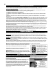
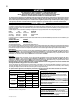
CONTINENTAL® products are manufactured under the strict Standard of the world recognized ISO 9001 : 2000 Quality Assurance Certifcate. CONTINENTAL® products are designed with superior components and materials, assembled by trained craftsmen who take great pride in their work. The burner and valve assembly are leak and test-fired at a quality test station.
GENERAL INSTRUCTIONS THIS GAS FIREPLACE SHOULD BE INSTALLED AND SERVICED BY A QUALIFIED INSTALLER to conform with local codes. Installation practices vary from region to region and it is important to know the specifics that apply to your area, for example: in Massachusetts State: • The fireplace damper must be removed or welded in the open position prior to installation of a fireplace insert or gas log.
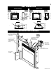
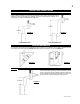
UNIT DIMENSIONS BCDV36CF(G) FIGURE 1 BCDV42CF FIGURE 2 38 1/2" 33" FIGURE 5 FIGURE 4 41 1/2" 35 1/2" 24 1/4" 34" GAS INLET 5 1/2" 37" 5 1/2" 3" 3" ELECTRICAL INLET LEFT SIDE FIGURE 6 FIGURE 3 5" DIA. 8" DIA. 27" T GAS INLET 4" DIA. 7" DIA.
VENTING THE BCDV36CF(G) USES: 4" EXHAUST / 7" AIR INTAKE VENT PIPE THE BCDV42CF USES: 5" EXHAUST / 8" AIR INTAKE VENT PIPE MODEL BCDV36CF MAY BE VENTED EITHER AS A TOP VENT OR A REAR VENT. REFER TO THE SECTION APPLICABLE TO YOUR INSTALLATION. For safe and proper operation of the fireplace follow the venting instruction exactly. Deviation from the minimum vertical vent length can create difficulty in burner start-up and/or carboning.
FIGURE 8 W415-0680 / 04.10.
TYPICAL MINIMUM AND MAXIMUM VENT LENGTHS BCDV36CF(G) REAR EXIT TOP EXIT 24" MAX 16" MINIMUM 16" MINIMUM 20" MAX 10" MIN 43" MINIMUM PLUS RISE* 40 FT MAX 3 FT MIN 40 FT MAX 3 FT MIN 33" 24 1/2" MINIMUM PLUS RISE* FIGURE 11 FIGURE 10 FIGURE 9 For optimum performance, it is recommended that all horizontal runs have a 1" rise per foot. When terminating vertically, the vertical rise is a minimum 3 feet and a maximum 40 feet from the centre of the fireplace flue outlet.
SPECIAL VENT INSTALLATIONS PERISCOPE TERMINATION BCDV36CF(G) Use the GD201 periscope kit to locate the air termination above grade. The periscope must be installed so that when final grading is completed, the bottom air slot is located a minimum of 12" above grade. The maximum allowable vent length is 10'.
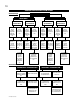
VENTING APPLICATION FLOW CHART BCDV36CF(G) FIREPLACE VENT EXIT TOP EXIT REAR EXIT Horizontal Termination Vertical Termination Horizontal Termination Vertical Termination Vertical rise is equal to or greater than the horizontal run Vertical rise is less than horizontal run Vertical rise is equal to or greater than the horizontal run Vertical rise is less than horizontal run Vertical rise is equal to or greater than the horizontal run Vertical rise is less than horizontal run Vertical rise is e
DEFINITIONS for the following symbols used in the venting calculations and examples are: > - greater than > - equal to or greater than < - less than < - equal to or less than HT - total of both horizontal vent lengths (HR) and offsets (HO) in feet HR - combined horizontal vent lengths in feet HO - offset factor: .03 (total degrees of offset - 90°*) in feet VT - combined vertical vent lengths in feet ELBOW VENT LENGTH VALUES feet 0.03 0.45 0.9 1.35 2.7 1° 15° 30° 45°* 90°* inches 0.5 6.0 11.0 16.0 32.
BCDV36CF(G) TOP EXIT / HORIZONTAL TERMINATION when (HT) > (VT) Simple venting configuration (only one 90° elbow) FIGURE 22 See graph to determine the required vertical rise VT for the required horizontal run HT. The shaded area within the lines represents acceptable values for HT and VT . REQUIRED VERTICAL RISE IN INCHES VT HORIZONTAL VENT RUN PLUS OFFSET IN FEET HT For vent configurations requiring more than one 90° elbow the following formulas apply: Formula 2: HT + VT < 24.
BCDV36CF(G) REAR EXIT / HORIZONTAL TERMINATION when (HT) < (VT) FIGURE 25 Simple venting configuration (only two 90° elbows) See graph to determine the required vertical rise VT for the required horizontal run HT REQUIRED VERTICAL RISE IN FEET VT HORIZONTAL VENT RUN PLUS OFFSETS IN FEET HT The shaded area within the lines represents acceptable values for HT and VT .
when (HT) > (VT) FIGURE 27 Simple venting configuration (only two 90° elbows) See graph to determine the required vertical rise VT for the required horizontal run HT REQUIRED VERTICAL RISE IN INCHES VT HORIZONTAL VENT RUN PLUS OFFSETS IN FEET HT The shaded area within the lines represents acceptable values for HT and VT . 90° For vent configurations requiring more than two 90° elbows the following formulas apply: Formula 1: HT < 3.5VT 90° Example 5: V1=4 ft V2=1.5 ft VT=V1 + V2 = 4 + 1.5 = 5.
BCDV36CF(G) TOP OR REAR EXIT VERTICAL TERMINATION when (HT) < (VT) Simple venting configuration (only two 90° elbows) FIGURE 29 REQUIRED VERTICAL RISE IN FEET VT HORIZONTAL VENT RUN PLUS OFFSET IN FEET HT The shaded area within the lines represents acceptable values for HT and VT .
when (HT) > (VT) FIGURE 31 Simple venting configurations See graph to determine the required vertical rise VT for the required horizontal run HT. MAXIMUM VERTICAL RISE IN FEET VT HORIZONTAL VENT RUN PLUS OFFSET IN FEET HT The shaded area within the lines represents acceptable values for HT and VT .
BCDV42CF HORIZONTAL TERMINATION when (HT) < (VT) Simple venting configuration (only one 45º and 90° elbow) 90° FIGURE 34 REQUIRED VERTICAL RISE IN FEET (VT) CALCULATED HORIZONTAL VENT RUN PLUS OFFSETS IN FEET (HT) The shaded area within the lines represents acceptable values for HT and VT . 45° For vent configurations requiring more than one 45º and 90° elbow, the following formulas apply: Formula 1: HT < VT Formula 2: HT + VT < 40 feet 90° Example 1: V1 = 8 ft VT V1= 8 ft H1 = 2.
For vent configurations requiring more than one 45º and one 90° elbow the following formulas apply: Formula 2: HT + VT < 24.75 feet Formula 1: HT < 4.2 VT Example 2: 90° 90° V1 = 4 ft V2 = 1.5 ft VT = V1 + V2 = 4 + 1.5 = 5.5 ft H1 = 2 ft H2 = 1 ft H3 = 1 ft H4 = 1.5 ft HR = H1 + H2 + H3 + H4 = 2 + 1 + 1 + 1.5 = 5.5 ft HO = .03 (one 45° elbow + four 90° elbows - 135°) = .03(405 - 135) = 8.1 ft HT = HR + HO = 5.5 + 8.1 = 13.6 ft HT + VT = 13.6 + 5.5 = 19.
BCDV42CF VERTICAL TERMINATION when (HT) > (VT) Simple venting configurations FIGURE 40 See graph to determine the required vertical rise VT for the required horizontal run HT. MAXIMUM VERTICAL RISE IN FEET VT HORIZONTAL VENT RUN PLUS OFFSET IN FEET HT The shaded area within the lines represents acceptable values for HT and VT .
BCDV36CF(G) PRE-INSTALLATION PREPARATION (THIS PROCEDURE IS NOT REQUIRED FOR THE BCDV42CF) For optimum performance, it is recommended that all horizontal runs have a 1" rise per foot. REMOVING THE VALVE ACCESS DOOR 1. The valve access door rotates on the pins attached to the side frame. Lift the valve access door off the pins to operate the main glass door. FIGURE 43 DOOR OPERATION FIGURE 44 To access the lower door latch, open the Valve Access Door as illustrated.
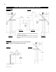
BCDV42CF HORIZONTAL VENT SECTIONS: A minimum clearance of 2" all around the vent pipe on all horizontal runs to combustibles is required. Use firestop spacer W010-1778 (supplied). VERTICAL VENT SECTIONS: A minimum of 1" all around the vent pipe on all vertical runs to combustibles is required. Use firestop spacer W500-0028 (not supplied). HORIZONTAL INSTALLATION FIGURE 47 BCDV36CF(G) ONLY This application occurs when venting through an exterior wall.
VERTICAL INSTALLATION 1. Determine the air terminal location, cut and frame 9 3/4" for the BCDV36CF(G), or 10 3/4" for the BCDV42CF square opening in the ceiling and an opening in the roof to provide the minimum 1" clearance between the fireplace vent pipe and any combustible material. Try to center the exhaust pipe location midway between two joists to prevent having to cut them. Use a plumb bob to line up the center of the openings. DO NOT FILL THIS SPACE WITH ANY TYPE OF MATERIAL.
5. Using the air intake vent pipe, slide over the fireplace combustion air collar and secure with 3 #8 screws. Seal with high temperature sealant W573-0002 (not supplied). 6. If more flexible vent pipe needs to be used to reach the fireplace, coupler them together as illustrated in Figure 59. The vent system must be supported approximately every 3 feet for both vertical and horizontal runs. Use noncombustible strapping to maintain the minimum 1" clearance to combustibles. 7.
EXTENDED HORIZONTAL AND CORNER AIR TERMINAL INSTALLATION 1. Follow the instructions for "Horizontal Air Terminal Installations", items 1 to 3. 2. Continue adding components alternating inner and outer venting. Ensure that all exhaust venting and elbows have sufficient vent spacers attached and each component is securely fastened to the one prior. Attach the exhaust telescopic sleeve to the vent run. Repeat using a air intake vent pipe telescopic sleeve. Secure and seal as before.
RESTRICTING VERTICAL VENTS BCDV42CF ONLY: Vertical terminations may display a very active flame. As this appearance is not desirable, the vent exit must be restricted using restrictor plate, W500-0205. This reduces the velocity of the exhaust gases, slowing down the flame pattern and creating a more traditional appearance. The plate has a series of holes to allow for adjustment. Remove the two screws on either side of the exhaust collar inside the firebox. Install the plate as shown.
FRAMING MINIMUM CLEARANCE TO COMBUSTIBLE CONSTRUCTION FROM FIREPLACE AND VENT BCDV36CF(G) SURFACES: Non-Combustible framing: Top 0" to stand-offs if using optional clean face surround Combustible framing: Sides, back, and bottom of the unit 0" to stand-offs* Top 3 1/2" to stand-offs if using optional clean face surround Non-combustible finishing: Top 6 1/2" if using optional clean face surround Combustible fireplace finishing: Sides, bottom and top 0" to fireplace edge Enclosure top 8 1/4" to top of fireplace
INSTALLING STANDOFFS Both the BCDV36CF(G) and BCDV42CF are supplied with two standoffs. For convenience, the standoffs have been shipped flat and located on the top at the front. Before framing ensure the standoffs are bent up and screwed into place ensuring a height of 4.5". FIGURE 66 BCDV36CF ILLUSTRATION NOTE: The information and dimensions in this section represent the minimum clearances to combustible material.
BCDV42CF BCDV36CF(G) 40 1 59 /2" ” 46 /1 64 2" " 45" 41 3/8" FIGURE 69 17 1/4" INSIDE CHASE 40 1/2" FIGURE 73 INSIDE CHASE 25 1/4" 6" FIGURE 70 FIGURE 74 OUTSIDE CHASE 17 1/4" 46 1/2" 6" OUTSIDE CHASE 25 1/4" 40 1/2" FIGURE 71 46 1/2" FIGURE 75 Warning: Non-combustible Finishing Materials Required Non-combustible materials such as brick and tile can be extended over the black face of the unit.
BCDV36CF(G) MINIMUM MANTEL AND ENCLOSURE CLEARANCES Combustible mantel clearance can vary according to the mantel depth. Use the graph to help evaluate the clearance needed. FIGURE 80 FIGURE 77 The fireplace requires a minimum enclosure height of 38 1/2“ (REAR VENT) 49" (TOP VENT). For temperature requirements, the enclosure space around and above the fireplace must be left unobstructed.
OPTIONAL CLEAN FACE SURROUND INSTALLATION BCDV36CF(G) ONLY FIGURE 83 FIGURE 84 FIGURE 85 CONCAVE S36CCN (BROWN) S36CCP (PEWTER) CONVEX S36CVN (BROWN) S36CVP (PEWTER) WAVE S36WN (BROWN) S36WP (PEWTER) ! WARNING Installation requires a minimum of 6 1/2" non-combustible facing material at the top of the fireplace. Refer to either Figure 86a or Figure 86b (depending on your installation) to ensure your fireplace has been installed with the proper requirements for this kit.
STEEL HEADER INSTALLATION FIGURE 87b FIGURE 87a 14” MIN 1 1/2” MAX 2 40 1/4” Concave Clean Face Surround Kit Illustrated 3 1 OPTIONAL CLEAN FACE TRIM KIT INSTALLATION The “wave” clean face surround kit is shown in all illustrations. NOTE: THE OPTIONAL CLEAN FACE TRIM KIT MUST BE INSTALLED BEFORE PROCEEDING. 1.
The fireplace requires a minimum enclosure height of 49“. For temperature requirements, the enclosure space around and above the fireplace must be left unobstructed. FIGURE 94b This fireplace requires a minimum of 6 1/2" of cement board or non-combustible equivalent above the top of the fire place. FIGURE 94a BCDV36CF FINISHING LOG PLACEMENT TM PHAZER logs and glowing embers exclusive to Wolf Steel Ltd., provide a unique and realistic glowing effect that is different in every installation.
BCDV36CF(G) GLASS/DOOR REPLACEMENT 1. Place the door frame face down careful not to scratch the paint. FIGURE100 2. Center the gasketed glass inside the door frame with the thick side of the gasket facing up. 3. Bend the glass retainers located along the edge of the door frame over the gasket holding the glass in place. Careful not to break the glass. BCDV42CF FINISHING DOOR INSTALLATION / REMOVAL Open the Valve Access Door.
GRATE INSTALLATION GRATE The grate for this fireplace has been removed for shipping purposes. The grate must be installed before the logs are installed. Remove the packaging from the grate and install onto the two pins as illustrated. PIN S FIGURE 104 LOG PLACEMENT TM PHAZER logs and glowing embers, exclusive to Wolf Steel Ltd., provide a unique and realistic glowing effect that is different in every installation. Take the time to carefully position the glowing embers for a maximum glowing effect.
LOGO PLACEMENT Remove the backing of the logo supplied and place on the glass viewing door, as indicated. ½" LOGO ½" FIGURE 109 BCDV36CFG FINISHING GLASS BURNER INSTALLATION FIGURE 110 Spread the clear glass embers (W300-0102) onto the glass ember tray evenly covering the burner tube (follow natural shape of tray). NOTE: The distribution of clear glass embers over the burner tube will influence the flame height. BULB REPLACEMENT The BCDV36CFG comes equipped with our “Night Light™”.
OPTIONAL BLOWER INSTALLATION BCDV36CF(G) ACCESSING THE BLOWER 1. Remove the valve access door. FIGURE 113a 2. Open the main door. 3. Carefully remove the logs. 3a. (BCDV36CFG) Carefully remove the glass and glass ember tray. 4. Remove the 7 screws illustrated in Fig. 113a and lift out the log support. FIGURE 113b 4a. (BCDV36CFG) Remove the top deflector and porcelain panels from the firebox. (See Figure 110). 5. Remove the 8 perimeter screws as illustrated in Fig. 113a and lift out the burner base.
Tilt the blower onto its side. Slide it past the controls and into the clip (C). Secure to the threaded stud using the lock washer and wing nut provided. Ensure that the blower does not touch the fireplace base or the firebox. Attach the connectors from the black and white wires to the thermodisc and secure the thermodisc bracket to the securing stud at the bottom left of the unit using a lock washer and wing nut. Ensure that the thermodisc touches the firebox wall.
BCDV36CFG BURNER SWITCH / WIRING DIAGRAM A wall switch must be installed in a convenient location for the burner operation. The recommended maximum lead length depends on wire size: WIRE SIZE MAX. LENGTH 14 gauge 100 feet 16 gauge 60 feet 18 gauge 40 feet A 20’ length of millivolt wire is connected to the gas valve control module wire harness for the burner wall switch.
BCDV36CFG LIGHT SWITCH / WIRING DIAGRAM A wall switch must be installed in a convenient location for the light operation. The recommended maximum lead length depends on wire size: WIRE SIZE MAX. LENGTH 14 gauge 100 feet 16 gauge 60 feet 18 gauge 40 feet A 20’ length of millivolt wire is connected to the terminal block for the light wall switch. However if a greater length is required route 2-strand (solid core) wire through the electrical hole located at the bottom left side of the unit.
RECEPTACLE WIRING DIAGRAM FIGURE 127 OPERATION BCDV36CF & BCDV42CF Purge all gas lines with the glass door of the fireplace removed or opened. Assure that a continuous gas flow is at the burner before installing the door. When lit for the first time, the fireplace will emit a slight odour for a few hours. This is a normal temporary condition caused by the "burn-in" of internal paints and lubricants used in the manufacturing process and will not occur again.
OPERATION BCDV36CFG FOR YOUR SAFETY READ BEFORE OPERATING ! WARNING IF YOU DO NOT FOLLOW THESE INSTRUCTIONS EXACTLY, A FIRE OR EXPLOSION MAY RESULT CAUSING PROPERTY DAMAGE, PERSONAL INJURY OR LOSS OF LIFE. A. THIS FIREPLACE IS EQUIPPED WITH AN IGNITION DEVICE WHICH AUTOMATICALLY LIGHTS THE PILOT. DO NOT TRY TO LIGHT BY HAND. B. BEFORE OPERATING SMELL ALL AROUND THE FIREPLACE AREA FOR GAS AND NEXT TO THE FLOOR BECAUSE SOME GAS IS HEAVIER THAN AIR AND WILL SETTLE ON THE FLOOR. C.
ADJUSTMENTS PILOT BURNER ADJUSTMENT EXCLUDING BCDV36CFG Adjust the pilot screw to provide properly sized flame. Turn in a clockwise direction to reduce the gas flow. FIGURE 128 FIGURE 129 VENTURI ADJUSTMENT These settings are for (maximum) horizontal termination. Adjustment may be required depending on fuel type, vent configuration and altitude. FIGURE 130 Closing the air shutter 1/16" 0 NG 1/4" will cause a more yellow flame, but can lead 1/4" 0 LP 7/16" to carboning.
FLAME ADJUSTMENT Turn clockwise to increase flame height FLAME ADJUSTMENT KNOB IH LO FIGURE 134 For BCDV36CFG For BCDV36CF and BCDV42CF BCDV36CF FLAME CHARACTERISTICS It is important to periodically perform a visual check of the pilot and the burner flames. Compare them to the figures shown. If any flames appear abnormal call a service person. 3/8” - 1/2” FIGURE 136 FIGURE 135 BCDV42CF FLAME CHARACTERISTICS It is important to periodically perform a visual check of the pilot and the burner flames.
COMMON REPLACEMENTS Contact your dealer for questions concerning prices and availability of replacement parts. Normally all parts can be ordered through your Authorized dealer or distributor. When ordering replacement parts always give the following information: 1. MODEL & SERIAL NUMBER OF FIREPLACE 2. INSTALLATION DATE OF FIREPLACE 3. PART NUMBER 4. DESCRIPTION OF PART 5. FINISH 6. TOP OR REAR VENT ! * IDENTIFIES ITEMS WHICH ARE NOT ILLUSTRATED.
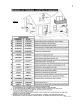
BCDV42CF REPLACEMENTS BCDV42CF COMPONENTS: 89 89 90 91 92 93 94 95 96 97 98 99* 100 100 101 102* W455-0019 W455-0003 W010-0864 GL-641 W135-0198 W135-0201 W135-0203 W135-0199 W135-0200 W010-1819 W010-1778 W500-0205 W585-0138 W655-0222 W185-0020 W550-0002 #43 NATURAL GAS ORIFICE #54 PROPANE GAS ORIFICE PAN BURNER LOG SET BACK LOG (#1) LEFT CROSSOVER LOG (#4) RIGHT CROSSOVER LOG (#5) SMALL LEFT LOG (#2) SMALL RIGHT LOG (#3) BLACK DOOR C/W GLASS FIRESTOP SPACER RESTRICTOR PLATE VENT HEAT SHIELD, TOP PIECE
W415-0680 / 04.10.
BCDV36CFG TROUBLE SHOOTING GUIDE BEFORE ATTEMPTING TO TROUBLESHOOT, PURGE YOUR UNIT AND INITIALLY LIGHT THE PILOT AND THE MAIN BURNER WITH THE GLASS DOOR REMOVED. SYMPTOM PROBLEM TEST SOLUTION Pilot will not light Wiring - Verify the "S" wire for the sensor and the "I" wire for the ignitor are connected to the correct terminals (not reverse) on the module and pilot assembly.
BCDV36CFG TROUBLE SHOOTING GUIDE SYMPTOM PROBLEM TEST SOLUTION Carbon is being deposited on glass, logs or combustion chamber surfaces. Air shutter has become blocked - Ensure air shutter opening is free of lint or other obstructions. Flame is impinging on the logs or combustion chamber. - Check that the logs are correctly positioned. - Open air shutter to increase the primary air. - Check the input rate: check the manifold pressure and orifice size as specified by the rating plate values.
BCDV36CF / BCDV42CF TROUBLE SHOOTING GUIDE SYMPTOM Pilot will not light PROBLEM No Spark at pilot burner TEST SOLUTION - Check if pilot can be lit by a match Check that the wire is connected to the push button igniter. Check if the push button igniter needs tightening. Replace the wire if the wire insulation is broken or frayed. Replace the electrode if the ceramic insulator is cracked or broken. Replace the push button igniter. Out of propane gas - Fill the tank.
Date Dealer Name Service Technician Name Service Performed This fireplace must be serviced annually depending on usage. Wolf Steel Fireplace Service History Special Concerns 50 W415-0680 / 04.10.
NOTES W415-0680 / 04.10.
NOTES W415-0680 / 04.10.