
Operating instructions


21
W415-0680 / 04.10.08
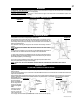
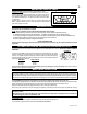
HORIZONTAL INSTALLATION
FIGURE 47
Apply a bead of caulking all around the edge of the opening and place the fi restop top, so that the vent shield covers the top of the vent
within the opening.
The length of the vent shield may be cut shorter for combustible walls that are less than 8 1/2" thick but the vent shield must extend the full
depth of the combustible wall.
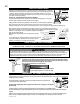
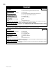
Place the fi restop bottom against the fi restop top and secure the two together. Adjust the assembly to ensure it is tight to the vent. Secure
fi restop to wall. Ensure that both spacer and shield maintain the required clearance to combustibles. Once the vent pipe is installed in
its fi nal position, apply
sealant between the vent
pipe and the fi restop
spacer. This restricts cold
air from being drawn into
the room or around the
fi replace. See Figures
49a-c.
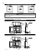
ADJUSTABLE FIRESTOP INSTALLATION
FIGURE 48
VENT
SHIELD
FIRESTOP
TOP
FIRESTOP
BOTTOM
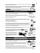
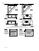
FIGURE 49a
FIGURE 49c
FIGURE 49b
BCDV42CF ONLY
BCDV36CF(G) ONLY
Where the opening in
the outside wall has
been cut 13" tall to pro-
vide 2" clearance from
the vent pipe, terminal extension plate W500-0206 must be used to cover the opening.
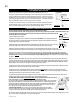
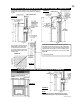
BCDV42CF
HORIZONTAL VENT SECTIONS: A minimum clearance of 2" all around the vent pipe on all horizontal runs to combustibles
is required. Use fi restop spacer W010-1778 (supplied).
VERTICAL VENT SECTIONS: A minimum of 1" all around the vent pipe on all vertical runs to combustibles is required. Use
fi restop spacer W500-0028 (not supplied).
This application occurs when venting through an exterior wall.
Having determined the correct height for the air terminal location, cut and frame a hole in
the exterior wall 9 7/8" wide by 11 3/8" high to accommodate the fi restop assembly. Dry
fi t the fi restop assembly before proceeding to ensure the brackets on the rear surface fi t
within the horizontal framing.
As an alternative to framing, the vent pipe can be enclosed in the wall using vent sleeve
VS47KT.
NOTE: THE FIRESTOP ASSEMBLY MUST BE INSTALLED WITH THE VENT SHIELD
TO THE TOP.
The length of the vent shield may be cut shorter for combustible walls that are less than 8
1/2" thick but the vent shield must extend the full depth of the combustible wall.
1. Apply a bead of caulking (not supplied) around the outer edge of the inside surface of
the fi restop assembly, fi t the fi restop assembly to the hole and secure using the 4 screws
(W415-0026) supplied in your manual baggy.
2. Once the vent pipe is installed in its fi nal position, apply high temperature sealant W573-
0002 (not supplied) between the pipe, and the fi restop.
NOTE: DO NOT FILL THE CAVITY BETWEEN THE VENT PIPE AND THE FIRESTOP SLEEVE WITH ANY TYPE OF
MATERIAL.