
Operating instructions


22
W415-0680 / 04.10.08
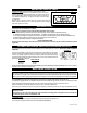
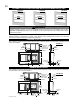
FIGURE 51
FIGURE 52
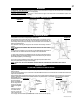
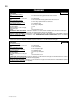
DO NOT FILL THIS SPACE WITH ANY TYPE OF MATERIAL.
A vent pipe shield will prevent any materials such as insulation, from fi lling up the 1" air space
around the pipe. Nail headers between the joist for extra support.
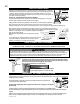
2. Apply a bead of caulking (not supplied) to the framework or to the Wolf Steel vent pipe shield
plate or equivalent (in the case of a fi nished ceiling), and secure over the opening in the ceiling.
A fi restop must be placed on the bottom of each framed opening in a roof or ceiling that the venting system passes through.
Apply a bead of caulking all around and place a fi restop spacer over the vent shield to restrict cold air from
being drawn into the room or around the fi replace. Ensure that both spacer and shield maintain the required
clearance to combustibles. Once the vent pipe is installed in its fi nal position,
apply high temperature sealant
W573-0002 (not supplied) between the vent pipe and the fi restop
spacer.
3. In the attic, slide the vent pipe collar down to cover up the open end
of the shield and tighten. This will prevent any materials, such as
insulation, from fi lling up the 1" air space around the pipe.
VERTICAL INSTALLATION
1. Determine the air terminal location, cut and frame 9 3/4" for the BCDV36CF(G), or 10 3/4" for
the BCDV42CF square opening in the ceiling and an opening in the roof to provide the minimum
1" clearance between the fi replace vent pipe and any combustible material. Try to center the
exhaust pipe location midway between two joists to prevent having to cut them. Use a plumb bob
to line up the center of the openings.
FIGURE 50
BCDV36CF(G) = 9 3/4”
BCDV42CF = 10 3/4”
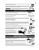
USING FLEXIBLE VENT COMPONENTS
THE BCDV36CF(G) USES: 4" EXHAUST / 7" AIR INTAKE VENT PIPE WITH A MINIMUM 6" BEND RADIUS
THE BCDV42CF USES: 5" EXHAUST / 8" AIR INTAKE VENT PIPE WITH A MINIMUM 8" BEND RADIUS
Use only approved fl exible liner kits marked:
"Wolf Steel Approved Venting" as identifi ed
by the stamp only on the 7" outer vent pipe.
ELBOW
SPACER
For safe and proper operation of the fi replace, follow the venting instructions exactly. All inner
exhaust and outer intake vent pipe joints may be sealed using either high temperature sealant
W573-0002 or high temperature Mill Pac W573-0007 with the exception of the fi replace exhaust
fl ue collar which must be sealed using Mill Pac (not supplied).
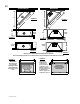
FIGURE 53
!
WARNING
Do not allow the inside liner to bunch up on horizontal or vertical runs and elbows. Keep it pulled tight. A 1 1/4" air gap
between the inner and outer fl exible vent pipe all around is required for safe operation. A spacer is required at the start, mid-
dle and end of each elbow to ensure this gap is maintained. See Figure 53. Spacers are attached to the inner fl ex liner at
predetermined intervals to maintain a 1 1/4" air gap to the outer fl ex liner. These spacers must not be removed.
A
T
T
E
N
T
I
O
N
-
C
H
A
U
D
C
A
U
T
IO
N
-
H
O
T
2” OVERLAP
HI-
TEMP
SEALAN
T
CAULK
ING
#10 X 2”
SCREWS
EXH
AU
ST
AIR
INTAKE VEN
T
PIPE
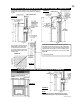
FIGURE 54
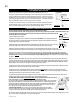
HORIZONTAL AIR TERMINAL INSTALLATION
1. Stretch the exhaust vent pipe to the required length taking into account the additional length needed for the fi nished wall surface. Slip the
vent pipe a minimum of 2" over the inner sleeve of the air terminal and secure with 3 #8 screws. Apply a heavy bead of the high temperature
sealant W573-0002 (not supplied).
2. Using the air intake vent pipe, slide over the outer combustion air sleeve of the air terminal and
secure with 3 #8 screws. Seal as before.
The air terminal mounting plate may be recessed into the exterior wall or siding by 1½", the depth of
the return flange.
3. Insert the fl exible vent pipe through the fi restop maintaining the required clearance to combustibles. Holding
the air terminal (lettering in an upright, readable position), secure to the exterior wall and make weather tight by sealing with caulking (not
supplied).
4. Apply a heavy bead of high temperature sealant W573-0007 (not supplied) to the outside of the 4" inner collar of the fi replace approxi-
mately 1" from the end. Slide the fl exible vent pipe a minimum of 2" over the fi replace vent collar and secure with 3 #8 screws.