
Operating instructions


23
W415-0680 / 04.10.08
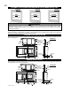
AIR INTAKE
VENT PIPE
EXHAUST
AIR INTAKE
VENT PIPE
COUPLER
COUPLER
#8 X 1/2”
SELF DRILLING
SCREWS & WASHERS
HI-TEMP
SEALER
FIGURE 58
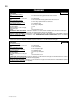
1. Fasten the roof support to the roof using the screws provided. The roof support is optional. In
this case the venting is to be adequately supported using either an alternate method suitable to the
authority having jurisdiction or the optional roof support.
2. Stretch the exhaust vent pipe to the required length, slip it a minimum of 2" over the inner sleeve
of the air terminal connector and secure with 3 #8 screws. Seal using a heavy bead of the high
temperature sealant W573-0002 (not supplied).
3. Repeat using air intake vent pipe.
4. Thread the air terminal pipe assembly down through the roof. The air terminal must be located vertically
and plumb. Attach the air terminal assembly to the roof support, ensuring that a minimum 16" of air termi-
nal will penetrate the roof when fastened.
DO NOT CLAMP THE FLEXIBLE VENT PIPE.
5. Remove nails from the shingles, above and to the sides of the chimney. Place the fl ashing over the air
terminal and slide it underneath the sides and upper edge of the shingles. Ensure that the air terminal is
properly centred within the fl ashing, giving a 3/4" margin all around. Fasten to the roof. Do NOT nail through
the lower portion of the fl ashing. Make weather-tight by sealing with caulking. Where possible, cover the
sides and top edges of the fl ashing with roofi ng material.
6. Aligning the seams of the terminal and air terminal connector, place the terminal over the air terminal connector making sure the
inner pipe goes into the hole in the terminal. Secure with screws provided.
7. Apply a heavy bead of weatherproof caulking 2" above the fl ashing. NOTE: Maintain a mini-
mum of 2" space between the air inlet base and the storm collar. Install the storm collar around the
air terminal and slide down to the caulking. Tighten to ensure that a weather-tight seal between the
air terminal and the collar is achieved.
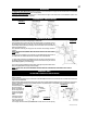
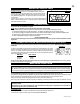
8. If more vent pipe needs to be used to reach the
fi replace, couple them together as illustrated. The
vent system must be supported approximately every
3 feet for both vertical and horizontal runs. Use
noncombustible strapping to maintain a clearance to
combustibles of 1".
VERTICAL AIR TERMINAL INSTALLATION
EXHAUST
VENT PIPE
AIR INTAKE
VENT PIPE
INNER
PIPE
HIGH
TEMPERATURE
SEALANT
AIR
TERMINAL
CONNECTOR
FIGURE 56
FIGURE 57
FIGURE 59
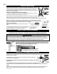
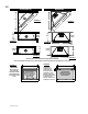
1. Move the fi replace into position. Measure the vent length required between terminal
and fi replace taking into account the additional length needed for the fi nished wall surface
and any 1¼" overlaps between venting components.
2. Apply high temperature sealant W573-0007 (not supplied) to the outer edge of the
exhaust vent pipe of the fi replace. Attach the fi rst vent component and secure using 3
self tapping screws. Repeat using air intake vent pipe and seal using high temperature
sealant W573-0002 (not supplied).
3. Holding the air terminal (lettering in an upright, readable position), insert into both vent
pipes with a twisting motion to ensure that both the terminal sleeves engage into the vent
pipes and sealant. Secure the terminal to the exterior wall and make weather tight by sealing with caulking (not supplied).
The air terminal mounting plate may be recessed into the exterior wall or siding by 1½", the depth of the return fl ange.
USING RIGID VENT COMPONENTS
HORIZONTAL AIR TERMINAL INSTALLATION
A
T
T
E
N
T
I
O
N
-
C
H
A
U
D
C
A
U
T
I
O
N
-
H
O
T
E
X
H
A
U
S
T
AIR
INTAKE
VENT PIPE
2” OVERLAP
H
I-
T
E
M
P
S
E
A
L
A
N
T
CAULKING
#10 X 2”
SCREWS
FIGURE 60
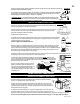
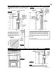
5. Using the air intake vent pipe, slide over the fi replace combustion air collar and secure with 3 #8 screws. Seal with high
temperature sealant W573-0002 (not supplied).
6. If more fl exible vent pipe needs to be used to reach the fi replace, coupler them together as illustrated in Figure 59.
The vent system must be supported approximately every 3 feet for both vertical and horizontal runs. Use noncom-
bustible strapping to maintain the minimum 1" clearance to combustibles.
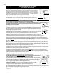
7. BCDV42CF ONLY: The vent heat shield must be installed only when terminating horizontally with no vertical
rise. Remove the two screws nearest the vent collars on the top of the fi replace. Align the vent heat shield (sup-
plied) and secure. Adjust the vent heat shield to touch the fi restop spacer.
VENT
HEAT
SHIELD
SCREWS
AD
JUST
TO
FIT
FIGURE 55