Operation, Installation and Instruction Manual for Reach-In Refrigerators and Freezers Continental Scientific A Division of National Refrigeration & Air Conditioning Products, Inc.
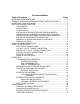
Operators Manual Table of Contents Page RECEIVING YOUR NEW MODEL........................................................................ 1 GENERAL INFORMATION AND IMPORTANT OPERATING FACTS ................. 1 UNCRATING YOUR NEW MODEL ...................................................................... 2 INSTALLATION AND LOCATION ........................................................................ 2 CLEARANCES...........................................................................................
TROUBLESHOOTING AND SERVICING GUIDE .............................................. 22 WIRING DIAGRAMS ..........................................................................................
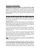
RECEIVING YOUR NEW MODEL Congratulations on your recent purchase of Continental Scientific superior laboratory/pharmacy equipment products! When your shipment arrives, please thoroughly examine the shipping crate for any punctures, dents, or signs of rough handling. It is in your best interest to partially remove or open the shipping container in order to examine the model for any concealed damages which may have occurred during shipment.
and sanitation, all models are listed under the reexamination service of underwriter's laboratories. UNCRATING YOUR NEW MODEL The shipping container should remain on your model as protection against dents or scratches while transporting it to the actual set-up location. Remove the shipping container only at the last possible moment by following these simple steps: 1. Using a pry bar, pry off and remove crate end bottom staples. 2. Pry off and remove crate front and rear bottom staples. 3.
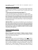
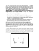
efficiency. Important Note: To assure sufficient air supply and circulation to the condensing unit, a minimum clearance of 12" above the grill and 3" on each side and back of the cabinet must be provided (see figure 1). If necessary, special venting or air supply ducts must be installed by the installer for this purpose. Do not at any time obstruct the grill area in front of the cabinet in any way, and never place or store anything on top of the cabinet machine compartment.
approximately 700 pounds of product (35 x 20) and assuming the refrigerator itself weighs 300 pounds, the total combined weight of cabinet and product is approximately 1000 pounds. Therefore, the floor in this example must be capable of supporting up to 1000 pounds. INSTALLING LEGS AND LEVELING REACH-IN MODELS Your new reach-in model is supplied with adjustable type legs for leveling purposes.
Your roll-in model comes with one cart ramp per door opening. To install the ramp(s), simply open the cabinet door and position the ramp slots onto the screws located along the cabinet bottom front. If the door wiper rubs along the ramp to the extreme where the door will not self-close, you will need to adjust the door (see "door adjustment" section) or level the cabinet as explained above.
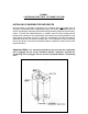
FIGURE 3 CASTERS MUST BE TIGHT TO CABINET BOTTOM INSTALLING CONDENSATE EVAPORATOR No floor drains or plumbing connections are required since all models use an automatic condensate water evaporating system. All models are supplied with an electric condensate evaporator pan and mounting bracket packed in the accessory carton. To install the condensate pan on models, remove both mounting screws located on the bottom of the cabinet back and install the mounting bracket on the case bottom as shown in figure 4.
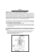
FIGURE 4 CONDENSATE EVAPORATOR INSTALLATION REMOVAL OF DOORS AND DOOR ADJUSTMENT During installation, it may become necessary to remove the cabinet doors to facilitate passage through narrow doorways or hallways. To remove a door, pry off all hinge covers using a sharp tool or knife (see figure 5). Swing the door to the open-door position (90 degrees) and carefully lift the door upward, removing the door from the hinge bodies.
FIGURE 5 DOOR ADJUSTMENT AND REMOVAL REMOVAL OF GRILL To remove the grill, loosen all four (4) grill mounting screws located on the backside of the grill one or two turns. Simply lift grill up off of its mounting screws and out. To replace the grill, line up the grill mounting screws with the keyhole slots located on the cabinet body, push in on the grill and down.
cleaning may result in a streaking or staining of the metal. Complete cleaning procedures and precautions are listed in the "periodic cleaning procedure" under the maintenance section. START-UP PROCEDURE ELECTRICAL CONNECTIONS To insure proper operation, your new model must be connected to an individual circuit that can supply the full voltage as stated on the cabinet serial data plate.
the condensing unit is 208-230 volts in which the wiring includes a neutral and a mechanical ground. This wiring should be connected to the appropriate power source by a qualified electrician and must conform to all local electrical codes. SPECIAL VOLTAGE CONNECTIONS When models are ordered from the factory with special, optional voltages, connections should be made as required on the electrical wiring diagram provided on the upper cabinet end panel next to the electrical console box.
condensing unit, and electrical hook-up should be performed by qualified refrigeration personnel of a competent refrigeration company only. OPERATION All cabinets must be given sufficient time to reach normal operating temperature before placing any product inside. Refrigerators are designed to maintain an ideal cabinet temperature of 3.3`c to 4.4`c (38`f to 40`f) and approximately 2 hours of operation are required to reach this temperature.
and turn the needle to the desired temperature using your fingers. Replace the lens cover and recheck the calibration. DIGITAL THERMOMETER For a digital thermometer, note how many degrees the digital display needs to be increased or decreased. Press twice directly on the mylar display towards the right center using your finger.
FIGURE 6 THERMOMETER CALIBRATION REFRIGERATOR SYSTEM AND ADJUSTMENT All self-contained refrigerators are designed and factory set to maintain an average cabinet temperature of 4`c. The temperature control is accessible from the top of the electrical console box located on the cabinet top behind the front grill (see figure 6).
compressor is not operating during an off-cycle. Do not set the thermostat too cold where the cabinet temperature will fall below 2`c because the evaporator will become blocked by ice since the compressor off-cycle will be considerably shortened. This will result in loss of product stored within the cabinet and require service to defrost the evaporator and re-adjust the thermostat.
cabinet temperature. On low-temperature freezers, place a screwdriver into the right thermostat adjustment screw (do not turn the left differential adjustment screw) and turn clockwise for a colder cabinet temperature or counterclockwise for a warmer cabinet temperature. Further adjustments out of the factory design temperature range must be made by a qualified refrigeration mechanic only.
FIGURE 8 DEFROST TIMER SETTING EVAPORATOR ASSEMBLY All refrigerators and freezers have an easily accessible, easily serviceable, performance rated, forced-air evaporator assembly which utilizes a plasticized fin coil for extended life (see figure 9). LOW-PROFILE, CEILING-MOUNT EVAPORATOR ASSEMBLY The low-profile evaporator system is comprised of a generous sized, evenly matched evaporator and air circulating fans contained within an easily accessible, low silhouette, interior ceiling mounted housing.
FIGURE 9 LOW-PROFILE,CEILING-MOUNT EVAPORATOR ASSEMBLY INTERIOR REACH-IN ACCESSORIES The standard interior accessory package that is supplied from the factory with your reach-in refrigerator or freezer consists of standard pilaster strips with pilaster clips (four (4)clips per shelf), three (3) epoxy coated shelves per section, and four (4) epoxy coated shelves per section on glass door models only.
the shelf on the clips as shown in figure 10. The standard pilaster and clip are shown in figure 10, and the optional heavy-duty pilaster and clip are shown in figure 11. Important Note: When loading shelves with product, allow space between rows of product for proper air circulation, and do not load product to block back wall (leave at least 2" of air space between product and back wall).
FIGURE 11 OPTIONAL HEAVY-DUTY PILASTER FIGURE 12 OPTIONAL ANGLE PAN SLIDES SAFETY PRECAUTIONS The following safety precautions should be followed when operating any appliances: ¬ Always disconnect the power cord before attempting to work on or clean - 19 -
any equipment. ¬ Disconnect the power cord when the appliance will be idled for a long period of time. ¬ Do not attempt to service this unit yourself as removing any covers may cause exposure to dangerous voltage. ¬ Always route the power cord so that it is not likely to be walked on or pinched by other appliances. Never use extension cords. ¬ Do not overload outlets with more than one appliance. This can result in fire or electrical shock. ¬ Your model is equipped with a grounded and polarized plug.
contact with stainless steel. 3. Tincture of iodine, or iron should not come in contact with stainless steel. These solutions, which cause stainless steel to discolor, should be rinsed off immediately if contact occurs. 4. Gritty, hard abrasives will mar the finish of stainless steel and aluminum and are not recommended. SLIDING AND HINGED GLASS All glass doors whether sliding or hinged are easily removable for cleaning.
this cleaning process. After cleaning, restore electrical service to your model. PARTS AND SERVICE Always provide the cabinet model and serial number (located on the data plate on the inside right wall of the cabinet) whenever contacting the factory or your dealer regarding questions or when ordering parts.
PROBLEM PROBABLE CAUSE CORRECTION Condensing unit will not start - no hum. 1.LINE DISCONNECTED, SWITCH OPEN. 1.CLOSE START OR DISCONNECT SWITCH. 2.REPLACE FUSE. 3.DETERMINE REASON AND CORRECT/REPLACE 4.RELOCATE CONTROL. 2.FUSE REMOVED OR BLOWN. 3.OVERLOAD PROTECTOR BLOWN. 4.CONTROL "OFF" DUE TO COLD LOCATION. 5.CONTROL STUCK IN OPEN POSITION. 6.WIRING IMPROPER OR LOOSE. Condensing unit will not start - hums but trips on overload protector.
PROBLEM PROBABLE CAUSE CORRECTION Condensing unit runs, but short cycles on: 1.OVERLOAD PROTECTOR. 2.THERMOSTAT. 3.HIGH PRESSURE CUT-OUT DUE TO: (a) INSUFFICIENT AIR SUPPLY. (b) OVERCHARGE. (c) AIR IN SYSTEM. 4.LOW PRESSURE CUT-OUT DUE TO: (a) VALVE LEAK. 1.SEE PROBLEM # 3. 2.DIFFERENTIAL MUST BE WIDENED. 3. (a) CHECK AIR SUPPLY TO CONDENSER. (b) EVACUATE AND RE-CHARGE. (c) EVACUATE AND RE-CHARGE. 4. (a) REPLACE, EVACUATE AND RECHARGE. (b) EVACUATE AND RE-CHARGE. (c) REPLACE EXPANSION DEVICE.
PROBLEM PROBABLE CAUSE CORRECTION Product zone temperature too high. 1.CONTROL SETTING TOO HIGH. 2.INADEQUATE AIR CIRCULATION. 1.ADJUST T-STAT 2.REARRANGE PRODUCT LOAD TO IMPROVE AIR CIRCULATION. 3.CLEAN CONDENSER COIL 3.DIRTY CONDENSER Suction line frosted or sweating. 1.OVERCHARGE OF REFRIGERANT. 2.EVAPORATOR FAN NOT RUNNING. 3.EXPANSION VALVE STUCK OPEN. 4.EXPANSION VALVE SUPERHEAT TOO LOW. Liquid line frosted, cold, or sweating. 1.RESTRICTION IN DRIER STRAINER. 2.
WIRING DIAGRAMS - 26 -
- 27 -
- 28 -
- 29 -
- 30 -
- 31 -
- 32 -
- 33 -