
Manual


30
FC2
FC1
Fig. 40
Fig. 42
6.2. DEFINITION OF OPENING DIRECTION AND OPERATION
OF LIMIT-SWITCH LEDS
Power up the system and set the opening direction on the
board (see par. 5.5.1).
If opening direction is
RIGHTWARD ( ):
OPENING limit-switch LED = FC1
CLOSING limit-switch LED = FC2
If opening direction is
LEFTWARD ( ):
OPENING limit-switch LED = FC2
CLOSING limit-switch LED = FC1
6. START-UP
6.1. ELECTRIC CONNECTIONS
Make all electrical connections to the board as in chapter 5,
including earthing of the operator (Fig. 40).
6.3. DETERMINING THE STOP POINTS AT TRAVEL LIMIT
Operator 746 has a limit sensor switch which, by detecting the
transit of a reference applied to the rack, commands the gate
motor to stop. The device can be MLS (fig. 41) or inductive (fig.
42).
6.3.1. MLS limit-switch
The MLS limit sensor switch detects the transit of two magnets
fitted on the side of the rack facing the operator.
Procedure for correct positioning of the two supplied magnets:
1) Check if the operator is in manual mode (see chapter 8).
2) Manually take the gate to opening position, leaving 2 - 5 cm
from the travel limit mechanical stop.
3) Fit the magnet (without removing the protective film from the
adhesive side) on the side of the rack facing the operator,
aligning the upper edges. Slide the magnet on the rack in
opening direction until the relevant LED goes off (Fig. 22 and
41), then move the magnet forward a further 45 mm.
4) Manually take the gate to closing position, leaving 2 - 5 cm
from the travel limit mechanical stop.
5) Fit the magnet (without removing the protective film from the
adhesive side) on the side of the rack facing the operator,
aligning the upper edges. Slide the magnet on the rack in
closing direction until the relevant LED goes off (Fig. 22 and 41),
then move the magnet forward by about a further 45 mm.
6) Take the gate to its halfway travel point and relock the system
(see chapter 9).
7) Find out the desired pre- and post-limit-switch deceleration
values (see parag. 5.5.2) and run the automated system for at
least one complete cycle.
8) Check if the gate stops at about 2 - 5 cm from its mechanical
stop point. If necessary, correct the position of the magnets
and check if the stop point is correct.
9) Mark the position of the magnets on the rack, and remove
them.
10) Clean the rack on its fitting points, remove the film on the
adhesive parts of the magnets (fig. 41 ref. 1) and re-position the
magnets with the adhesive strip in contact with the rack (fig. 41
ref. 2).
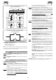
6.3.2. Inductive limit-switch
Operator 746 has an inductive limit-switch which detects the
transit of the two steel plates fitted on the top of the rack.
Procedure for correct positioning of the two supplied steel plates:
1) Assemble the limit-switch by centring the plate with respect to
threaded pins of the support (Fig. 42).
2) Check if the operator is in manual operating mode (see
chapter 8).
3) Manually move the gate to opening position, allowing 2 - 5 cm
from the mechanical stop limit.
4) Allow the plate to move on the rack in opening direction until
the relevant LED goes OFF (Figs. 22 and 42); next, move the
plate forward by about another 45 mm and secure it to the rack
by tightening the screws.
5) Manually move the gate to closing position, allowing 2 - 5 cm
from the mechanical stop limit.
6) Allow the plate to move on the rack in closing direction until the
relevant LED goes OFF (Figs. 22 and 42); next, move the plate
forward by about another 45 mm and secure it to the rack by
tightening the screws.
Attention: due to the powerful magnetic fields the supplied
magnets produce, the magnets can damage magnetic band
components (credit cards, magnetic tapes, floppy disks, etc)
and electronic and mechanical equipment (e.g. watches, LCD
screens). We advise you not to bring them near to objects that
could be damaged if 'immersed' in a magnetic field.
Notes on magnet positioning
• To ensure correct operation, allow at least 2 cm from the
mechanical stop limit in the gate stop position. Carry out this
check after determining the values of the pre- and post-limit
switch decelerations (see par. 5.5.2.) and after running at least
one complete cycle of the automated system.
• The distance between the limit-switch and magnets must be
from 5 to 12 mm.
• Magnets should be fitted on the rack and not on the fixing
screws.
If necessary, position the magnet at the side of the screw
and adjust decelerations (parag. 5.5.2) in order to obtain
the correct stop point.
2
1
FC2
FC1
Fig. 41