
Manual


32
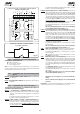
Fig. 50
Fig. 49
Fig. 48
Fig. 52
9. RESTORING NORMAL OPERATION
To prevent an involuntary pulse from activating the gate during the
manoeuvre, cut power to the system before re-locking the operator.
1) Re-close the release lever.
2) Turn the key anti-clockwise
3) Remove the key and close the lock protection door.
4) Move the gate until the release meshes.
8. MANUAL OPERATION
If the gate has to be operated manually due to a power cut
or malfunction of the automated system, use the release
device as follows:
1) Open the protection door and fit the supplied key in the
lock (Fig. 48).
2) Turn the key clockwise and pull the release lever as shown
in Fig. 49.
3) Open and close the gate manually.
10. INSTALLING THE CN 60E CONTROL UNIT (OPTIONAL)
The operator is designed to house (with the aid of a DIN bar)
the CN 60E control unit of the safety conductive edge. Cut the
DIN bar to measure and secure it to the operator with two
screws in the appropriate holes and attach the CN 60E control
unit to it (Fig. 50).
For connection and operation, refer to the specific instructions.
11.SPECIAL APPLICATIONS
There are no special applications.
12.MAINTENANCE
Check the operational efficiency of the system at least once
every 6 months, especially as regards the efficiency of the
safety and release devices (including operator thrust force).
12.2. OIL TOP-UPS
Periodically check oil level inside the operator.
A once-a-year check is enough for medium or low use frequency.
For heavier duty, every 6 months is recommended.
To access the tank, temporarily remove the oil filling plug (Fig.
52).
Oil level (visually checked) must be in line with the copper windings
of the electric motor.
To top up, pour in oil up to the required level.
Use FAAC XD 220 oil only.
12.1. DISASSEMBLING THE TRANSFORMER-BOARD UNIT
If you have to disassemble the transformer-board unit, proceed
as follows:
Remove all terminal boards and connectors from the board.
Unscrew the 3 securing screws of the board and the 2 of the
transformer. Lift the unit up and gently remove the transformer
from the couplings on the board as shown in Fig. 51.
13.REPAIRS
For any repairs, contact the FAAC authorised Repair Centres.
Fig. 47
Fig. 51