
Manual

21
AB
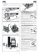
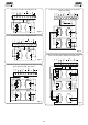
Fig. 8
Fig. 12
Fig. 10
Fig. 11
Fig. 9
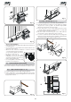
Fig. 13
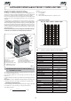
5) Secure the gearmotor to the foundation plate, tightening the
nuts as in Fig.12.
6) Prepare the operator for manual operating mode as described
in chapter 8.
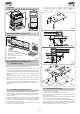
4.4. INSTALLING THE RACK
4.4.1. STEEL RACK TO WELD (Fig.13)
1) Place the three threaded pawls on the
rack element, positioning them at the
top of the slot. In this way, the slot play
will enable any adjustments to be
made.
2) Manually take the leaf into its closing
position.
3)
Lay the first piece of rack level on the
pinion and weld the threaded pawl
on the gate as shown in figure15.
4) Move the gate manually, checking if the rack is resting on the
pinion, and weld the second and third pawl.
5) Bring another rack element near to the previous one, using a
piece of rack (as shown in figure 16) to synchronise the teeth of
the two elements.
6) Move the gate manually and weld the three threaded pawls,
thus proceeding until the gate is fully covered.
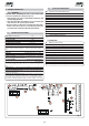
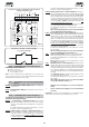
Fig. 14
4.4.2. STEEL RACK TO SCREW (Fig. 14)
1) Manually take the leaf into its closing position.
2) Lay the first piece of rack level on
the pinion and place the spacer
between the rack and the gate,
positioning it at the top of the slot.
3) Mark the drilling point on the gate.
Drill a Ø 6,5 mm hole and apply
thread with a Ø 8 mm male tap.
Screw the bolt.
4) Move the gate manually, checking
if the rack is resting on the pinion,
and repeat the operations at point
3.
5) Bring another rack element near to the previous one, using a
piece of rack (as shown in figure 16) to synchronise the teeth of
the two elements.
6) Move the gate manually and carry out the securing operations
as for the first element, thus proceeding until the gate is fully
covered.
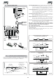
Fig. 14bis
4.4.3. NYLON RACK TO SCREW (Fig.14bis)
1) Manually take the leaf into its
closing position.
2) Lay the first piece of the rack level on
the pinion and mark the drilling point
on the gate; drill Ø 4 mm and screw
the self-tapping screw 6 x 20 mm to
the relevant reinforcing plate.
3) Move the gate manually, checking
if the rack is resting on the pinion,
and repeat the operations at point
2.
4) Bring another rack element near to the previous one, using
a piece of rack (as shown in figure 16) to synchronise the
teeth of the two elements.
5) Move the gate manually and carry out the securing
operations as for the first element, thus proceeding until the
gate is fully covered.