
Manual

22
Fig. 15
Fig. 16
Fig. 19
Fig. 21
Fig. 20
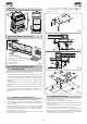
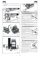
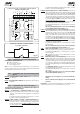
Notes on rack installation
• Make sure that, during the gate travel, all the rack elements do
not exit the pinion.
• Do not, on any account, weld the rack elements either to the
spacers or to each other.
• When the rack has been installed, to ensure it meshes
correctly with the pinion, we advise
you to lower the gearmotor position
by about 1.5 mm (Fig.17).
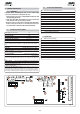
• Manually check if the gate
habitually reaches the mechanical
stop limits and make sure there is no
friction during gate travel.
• Do not use grease or other lubricants
between rack and pinion.
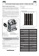
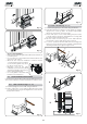
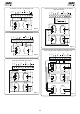
4.5. INSTALLATION OF CHAIN PINIONS
In the versions for applications with chain and idle transmissions,
a Z16 or Z20 chain pinion must be installed. Proceed as follows:
4.5.1. MOD. 746 ER CAT (Figs. 18 - 19)
1) Insert the spring pin on the shaft, using a hammer.
2) Fit the chain pinion on the shaft, making the pinion seats
coincide with the spring pin and tighten the screw with the
appropriate washers.
Fig. 17
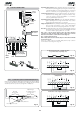
4.5.2. MOD. 746 ER RF (Figs. 20 - 21)
1) Insert the spring pin on the shaft, using a hammer.
2) Fit the idle transmissions bracket on the gearmotor flange,
using the four screws (M5 x 12) and the appropriate
washers , in the kit as shown in Fig. 20.
3) Fit the chain pinion on the shaft, making the pinion seats
coincide with the spring pin and tighten the screw and
the appropriate washers and .
4) Pass the chain as shown in Fig. 21 ref. A and install the
housing with screw and washer as in Fig. 20.
5) In case of operators with MLS limit switches, arrange the
supports for the positioning of the magnets supplied while
observing the dimensions given in fig. 21 ref. B.
0÷10 mm
5÷1
2
mm
Fig. 18
A
B