
Owner manual

Installation
Receiver Terminal Wiring
DoorKing Part Numbers
This receiver is NOT designed to be installed outdoors without being protected
from the weather. An outdoor enclosure is available for the receiver if required
(P/N 8057-110 - Metal Outdoor Box).
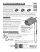
Install the 8054 receiver in a location so the antenna is NOT surrounded by
metal and is in free air as high as possible above the ground. A longer Coax
Antenna kit is available for the receiver if required (P/N 1514-073 - Includes
antenna, mounting “L” bracket and 15 feet of coax cable). An antenna amplifier
kit (P/N 8058-080) or a Yagi directional antenna kit (P/N 1514-072) is also
available for the receiver if required.
The RF LED on the side of the case will blink as RF energy is received.
If the LED blinks or is on continuously, this indicates that there may
be interference on the frequency (318 MHz) and short range may be
the result. If this happens, try relocating the receiver or remove the
source of interference. An antenna amplifier or a directional antenna
may be needed.
Note: Loop detectors and proximity card readers can cause receiver
interference.
120 Glasgow Avenue
Inglewood, California 90301
U.S.A.
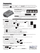
To Receiver Terminal #1 (Neg.)
To Receiver Terminal #2 (Pos.)
12-24 Volt
Transformer
Printer Interface Terminal P/N 1587-010
DC Polarity Matters!
Removable
receiver terminal
for easy wiring.
8054-081
50 Transmitter Codes
8054-082
100 Transmitter Codes
8054-083
250 Transmitter Codes
8054-084
500 Transmitter Codes
8054-085
1000 Transmitter Codes
8054-086
1250 Transmitter Codes
Printer: Connect receiver directly to a printer using the printer interface terminal
as shown.
• Maximum wire run for printer data is 500 ft using Belden 9931, Consolidated
5324-CL or equivalent shielded wire. DO NOT use twisted pair wire for printer data.
• Serial printer setting: 9600 baud, 1 start, 8 data, 1 stop.
#1 - Input Power 12-24 Volt AC, 12-24 Volt DC (Negative)
#2 - Input Power
12-24 Volt AC, 12-24 Volt DC (Positive)
#3 - Relay Contact (Normally Open)
#4 - Relay Contact (Normally Closed)
#5 - Relay Contact (Common)
#6 - Printer Data
(
P1 DoorKing Printer Interface Terminal)
#7 - Printer Signal Ground
(
P2 DoorKing Printer Interface Terminal)
#8 - Printer Busy
(
P3 DoorKing Printer Interface Terminal)
MODEL 8054 MicroPLUS
®
RF RECEIVER
The model 8054 is a High Security Encrypted “Rotating Code” RF Receiver that is designed for stand alone applications. The
encrypted “Rotating Code” programming in this receiver and the companion MicroPLUS
®
transmitters prevent copied transmitter
codes from being used again to access a controlled entry point. The 8054 receiver includes 10 time zones (eight programmable),
a history buffer that can store up to 2800 transactions in its memory. A serial printer can be connected to print the stored
transactions or the receiver can be programmed to print transactions in real time mode.
The MicroPLUS
®
transmitter codes that the
receiver will respond to can also be defined by
“Facility Codes”, and “Transmitter Button
Codes”. For example: an 8054 receiver can be
programmed to respond to only the first button
on a multiple button MicroPLUS
®
transmitter while a second 8054 receiver can be programmed to respond to only the second button of the same
multiple button MicroPLUS
®
transmitter. Thus allowing a single multiple button MicroPLUS
®
transmitter to activate two different receivers
without fear of both receivers responding to the same transmitter code. There are three (3) different “2 Button” MicroPLUS
®
transmitter button
combinations that each receiver can be programmed to respond to: button-1, button-2 and buttons 1&2 pressed at the same time. There are six
(6) different “3 Button” MicroPLUS
®
transmitter button combinations that each receiver can be programmed to respond to: button-1, button-2,
button-3, buttons 1&2 pressed at the same time, buttons 2&3 pressed at the same time and buttons 1&3 pressed at the same time.
P/N 8069-080 P/N 8070-080 P/N 8071-080
1
Butto
n
2
Butto
n
3
Butto
n
Use ONLY MicroPLUS
®
Transmitters
1
2
3
4
5
6
7
8
Receiver
Terminal
RF LED
Mas
t
e
r Code
B
utton
(S
e
e next page)
Coax
Antenna
Kit
(Included)
18”
Coax
Cable
Terminals 3-4-5
rated for 30 volt,
1 amp max.
25-Pin Connector
#
*
1
2
3
4
5
6
7
8
9
0
To Receiver Terminal #6
To Receiver Terminal #7
To Receiver Terminal #8
P1
P2
P3
To Printer
Printer
Cable
Not
Supplied
Stand-Alone Power and Device Wiring :
Connect 12 - 24 Volt AC or DC power to terminals #1 and #2. Use minimum 18 AWG wire to power the receiver.
•
If DC power is used (Transformer): Terminal #1 is NEGATIVE and Terminal #2 is POSITIVE.
• Connect the receiver relay contacts to the device to be activated.
- Receiver Terminal #3 is the relay contact Normally OPEN (N.O.)
- Receiver Terminal #4 is the relay contact Normally CLOSED (N.C.)
- Receiver Terminal #5 is the relay contact Common (C).