INSTALLATION, OPERATION & MAINTENANCE MANUAL SINGLE PACKAGED ROOF TOP AIR CONDITIONERS 'PT' SERIES MODELS: PT036 - PT360 Part Number: 800-213-03
INDEX Contents Page General Model decoding ...................................................................................................................................................... 2 General statement .................................................................................................................................................. 3 Warranty ..........................................................................................................................................
2 Y : 1 HP ODP 060 PT 360 300 240 215 180 120*** 100 090 075 L : 380/415-3-50 (4 WIRE) 6 ELECTRICAL SUPPLY ( V-Ph-Hz ) ** *** D : DUAL S : SINGLE 7 REFRIGERATION CIRCUIT – 3 HP motor only available for PT120. – Applicable for models PT180 & above only. NOTE: * – Applicable for PT075 models only. COOLINE PACKAGED UNIT 3, 4 & 5 NOMINAL COOLING CAPACITY (MBH) P : 15 HP TEFC N : 15 HP ODP M : 10 HP TEFC L : 10 HP ODP M : 10 HP TEFC L : 10 HP ODP K : 7.5 HP TEFC J : 7.
GENERAL GENERAL STATEMENT This unit is from the PT series that was designed & built for the optimum performance. However, it is required that you become well acquainted with good practices for the proper installation/operation/and maintenance procedures in order to ensure a safe trouble free operation, year after year. Please read through the whole manual contents before you attempt to install/operate/ and maintain the unit.
INSTALLATION INSTRUCTIONS GENERAL These units are shipped completely assembled, charged, and wired. They do not require any field installation of refrigerant tubing. Units require external power, thermostat wiring, condensate drain piping and ducting as applicable. Size of unit for an installation should be based on a heat gain calculation made according to applicable standards.
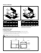
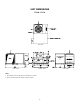
SERVICE CLEARANCE MODELS: PT036 - PT120 MODELS: PT180 - PT360 D D E C C A A B B NOTE: Only two condenser fans for models PT180 - PT240. NOTE: All dimensions are in cm.
CONDENSATE DRAIN CONNECTION • • • Use standard PVC pipe with NPT connection for the condensate drain. Provide a 'P' trap immediately at the condensate drain connection. Piping has to be sloped away from the unit. Remember to remove the drain hole plug before operating the unit. Avoid bends & elbows. DUCT CONNECTION The units can be connected to the ducting in horizontal configuration. Connect ducting using flexible duct connection.
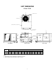
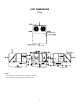
UNIT DIMENSIONS AIR IN PT036 - PT075 COMPRESSOR/CONTROL COMPARTMENT POWER SUPPLY INLET AIR IN CONDENSER COIL CONDENSATE DRAIN OUTLET [BOTH ENDS] TOP VIEW K SUPPLY AIR OPENING FILTER ACCESS PANEL [BOTH ENDS] J SUPPLY AIR ACCESS PANEL FOR BLOWER AND MOTOR CONDENSER COIL RETURN AIR OPENING FRESH AIR OPENING COMPRESSOR/CONTROLS ACCESS PANEL DRAIN OUTLET [BOTH ENDS] 51 [2.00] 15 [0.59] 61 [2.41] 286 [11.27] SIDE VIEW 90 [3.
UNIT DIMENSIONS PT090 - PT120 TOP VIEW SIDE VIEW FRONT VIEW NOTE: 1. All dimensions are in mm (dimensions in brackets are in inches). 2. Service clearance should be 1200mm (4 feet) on all sides.
UNIT DIMENSIONS PT180 TOP VIEW SIDE VIEW FRONT VIEW NOTE: 1. All dimensions are in mm (dimensions in brackets are in inches). 2. Service clearance should be 1200mm (4 feet) on all sides.
UNIT DIMENSIONS PT215 - PT240 TOP VIEW SIDE VIEW FRONT VIEW NOTE: 1. All dimensions are in mm (dimensions in brackets are in inches). 2. Service clearance should be 1200mm (4 feet) on all sides.
UNIT DIMENSIONS PT300 - PT360 TOP VIEW SIDE VIEW FRONT VIEW NOTE: 1. All dimensions are in mm (dimensions in brackets are in inches). 2. Service clearance should be 1200mm (4 feet) on all sides.
CABLE SIZE All wiring should be in accordance with local standards. Before making any connection, check the electric power supply, it must have the same characteristics as what is displayed in the nameplate. For selecting cable size, refer to wire ampacity table at different MCA (Minimum Circuit Amps) provided in unit electrical data, which is listed as a guideline (see table below). Wiring connection to the unit must have suitable insulation of a minimum temperature of 600C.
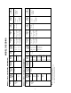
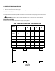
ELECTRICAL DATA MODELS: PT036 - PT060 POWER SUPPLY (V-Ph-Hz) MODEL NUMBER VOLTAGE RANGE MIN. 380/415-3-50 (4 WIRE) PT036 380/415-3-50 (4 WIRE) PT048 342 342 MAX. 457 457 FM FLA 2.3 2.3 COMPRESSOR BLOWER MOTOR RLA HP LRA 5.9 42 10.4 FLA 0.75 55 5.5 0.75 5.5 380/415-3-50 (4 WIRE) 342 457 2.3 9.6 65 1 7.8 MCA MOCP kW FLA – – 15.2 20 5/6 7.6/9.1 16.4/18.3 20/20 7.5/10* 11.4/15.2 21.1/25.9 25/30 12* 18.2 29.6 30 – – 20.8 30 5/6 7.6/9.1 20.8/20.
ELECTRICAL DATA MODELS: PT180 & PT215 MODEL NUMBER DESCRIPTION PT180 VOLTAGE RANGE POWER SUPPLY (V-Ph-Hz) Min. Max. FM (each) FLA COMPRESSOR (each) 380/415-3-50 (4 WIRE) 342 457 1.9 ELECTRIC HEATER BM RLA LRA HP FLA Nom. kW 5 9.2 17.3 111 & & 16.4 95 7.5 PT215 13 MCA MOCP FLA COMPRESSOR (each) ELECTRIC HEATER BM RLA LRA HP FLA Nom. kW MCA MOCP FLA – – 51 60 – – 56.2 70 7.5/10 11.4/15.2 51/51 60/60 7.5/10 11.4/15.2 56.2/56.2 70/70 10 /12 15.2/18.2 56.2/56.
Performex-1TM CONTROLLER : OPERATION & FUNCTIONS The COOLINE Packaged units are provided with technologically advanced new PerformexTM Controller Microprocessor Based Electronic Control Board, incorporating the following benefits and features: - COMPLETE UNIT CONTROL: Provides complete unit control for heating and cooling application whether single stage or two stage utilizing the input from sensor that measure temperatures during unit operation.
7. LEAD/LAG OPERATION: Whenever a compressor needs to be on, the controller will turn on the compressor with the shorter accumulated run time provided its 3 minutes minimum off time has lapsed. Otherwise the other compressor will on first. Similarly, the compressor with the longer accumulated run time will be the first one to be cut off. This is to load the compressors evenly over long run period. Balance loading is enabled when compressor #1 lead option is disabled. 8.
MAINTENANCE INSTRUCTIONS AIRFLOW ADJUSTMENT (Applicable for PT075 - PT360 only) The airflow could be adjusted by adjusting pulleys of blower motor or belt tension with proper mounting and alignment of the pulleys: • Refer to fan performance tables in the catalog for selecting applicable airflow, RPM and brake horse power at specified static pressure. • • • Select the appropriate drive as per motor and blower characteristic in the catalog. • • Tighten the set screw and then install the belts.
BELT TENSION TESTING PROCEDURE BELT SPAN 64 DEFLECTION = FORCE SCALE SMALL "0" RING BELT SPAN SPAN SCALE LARGE "0" RING BELT TENSION CHECKER MEASURE THE BELT DEFLECTION FORCE BELTS BELT TYPE BELT CROSS SECTION – 3L A 4L B 5L DEFLECTION FORCE - LBS. SMALL PULLEY PITCH DIA. (P.D.) RANGE MINIMUM MAXIMUM 1.25 – 1.75 2 – 2.25 2.5 – 3 2.1 – 2.8 3 – 3.5 3.7 – 5 3 – 4.2 4.5 – 5.
PREVENTIVE MAINTENANCE SCHEDULE CAUTION: Disconnect power supply and allow all rotating parts to stop before servicing the unit.
TROUBLE SHOOTING CHART SYMPTOM Thermostat shows no display CAUSES CHECK & CORRECTIVE MEASURE 2. Faulty field wiring 3. Loose connections 4. Defective thermostat 1. Check the power. Switch ON the circuit breaker. Replace fuse if it blown. 2. Check wiring against diagram. 3. Check and correct it. 4. Replace it. 1. Battery life is over 1. Replace battery 1. Blower belt slipped/not fixed 2. Faulty wiring 3. Burned wiring 4. Defective blower motor contactor 5. Defective blower motor 1. Correct belt.
TROUBLE SHOOTING CHART SYMPTOM Unit works continuously, no sufficient cooling CAUSES CHECK & CORRECTIVE MEASURE 1. Low suction pressure 2. High discharge pressure 3. Less air quantity 4. Cooling coil ices up 5. Second stage (If exists) not working Unit not cooling properly during night time 6. Serving large area 1. Low ambient condition 2. Safety low pressure switch open due to low suction pressure 3. Fan cycling (whenever applicable) setting low 4. Thermostat setting too low 5. Cooling coil ices-up 6.
TYPICAL SCHEMATIC WIRING DIAGRAM MODELS : PT036 - PT075 (Single compressor units) HEATER DATA TABLE (SEE HEATER DATA TABLE) HEATER CONNECTION DETAILS DIP SWITCH SETTINGS JUMPER SETTING ON ECB NOTE: 1. Refer to next page for legend, notes & wiring diagram for optional items. 2. Refer to unit control box (inside panel) for exact wiring diagram.
TYPICAL SCHEMATIC WIRING DIAGRAM MODELS : PT036 - PT075 (Single compressor units) LEGEND STANDARD OPTIONS 1. UVM OPTION * * 2. SMOKE DETECTOR OPTION * FACTORY INSTALLED B.M SPEED TO HVTB TO NTB * 3. VOLT FREE CONTACT OPTIONS A. UNIT ON & OFF INDICATION OPTION TO HVTB TO NTB * C. BM ON,OFF & TRIP INDICATION OPTION AR AFS ATB BM BMC CC CCA CB C.
TYPICAL SCHEMATIC WIRING DIAGRAM MODELS : PT090 - PT120 (Dual compressor units) NOTE: 1. Refer to next page for legend, notes & wiring diagram for optional items. 2. Refer to unit control box (inside panel) for exact wiring diagram.
TYPICAL SCHEMATIC WIRING DIAGRAM MODELS : PT090 - PT120 (Dual compressor units) CONNECTION APPLICABLE FOR 1PH FM ONLY TO HVTB L2 BM WITH EXTERNAL OLR 3. VOLT FREE CONTACT OPTIONS A. UNIT ON & OFF INDICATION OPTION TO NTB N CRANKCASE HEATER CONNECTION C. BM ON,OFF & TRIP INDICATION OPTION STANDARD OPTIONS 1. UVM OPTION FAN MOTOR CONTROL CONNECTION (APPLICABLE FOR FM WITH T.O.P) 2. SMOKE DETECTOR OPTION LEGEND AR AFS ATB BM BMC CC CCA CB C.
TYPICAL SCHEMATIC WIRING DIAGRAM MODELS : PT180 - PT240 (Dual compressor units) CONNECTION FOR COMPRESSOR WITH MOTOR OVERLOAD TO HVTB CONNECTION FOR SCROLL COMP. WITH SSPS HEATER DATA TABLE CONNECTION FOR MANUEROP COMP. WITH SSPS (SEE HEATER DATA TABLE) HEATER CONNECTION DETAILS 230V NOTE: 1. Refer to next page for legend, notes & wiring diagram for optional items. 2. Refer to unit control box (inside panel) for exact wiring diagram.
TYPICAL SCHEMATIC WIRING DIAGRAM MODELS : PT180 - PT240 (Dual compressor units) STANDARD OPTIONS LEGEND 1. UVM OPTION TO HVTB TO HVTB 2. SMOKE DETECTOR OPTION 3. VOLT FREE CONTACT OPTIONS A. UNIT ON & OFF INDICATION OPTION COMP. WITH CIRCUIT BREAKER OPTION HVTB LUG LOW AMBIENT OPTION AR AFS ATB BM BMC CC CCA CB C.
TYPICAL SCHEMATIC WIRING DIAGRAM MODELS : PT300 - PT360 (Dual compressor units) NOTE: 1. Refer to next page for legend, notes & wiring diagram for optional items. 2. Refer to unit control box (inside panel) for exact wiring diagram.
TYPICAL SCHEMATIC WIRING DIAGRAM MODELS : PT300 - PT360 (Dual compressor units) LEGEND AR AFS ATB BM BMC CC CCA CB C.
PARTS LIST MODEL NUMBER PT036L PT048L PT060L PT075L PT090 COMPRESSOR 800-684-08 800-672-52 800-643-01 800-674-78 800-684-09 800-672-52 800-674-25 800-674-67/81 800-674-38 FAN MOTOR 800-555-26 800-555-26 800-555-26 800-555-26 800-545-68 800-545-68 800-545-68 800-545-68 800-545-68 FAN MOTOR CAPACITOR 800-353-15 800-353-15 800-353-15 800-353-15 BlOWER MOTOR (STANDARD) 800-546-94 800-546-94 800-546-95 800-544-13 800-544-16 800-544-16 800-544-17 800-544-72 800-544-72 BLOWER WHEEL 800-707-10 800-707-1