Read and Retain for Future Reference Cooper Bussmann BU-245U-E Wireless Ethernet & Device Server User Manual Version 1.6 3A1576Rev1.
Cooper Bussmann BU-245U-E Wireless Ethernet & Device Server User Manual Cooper Bussmann Application Engineering • Phone 8:00 a.m - 5:00 p.m. Central, M-F (636) 527-1270 • Fax: (636) 527-1607 • E-mail: FuseTech@cooperindustries.com Thank you for your selection of the BU-245U-E Wireless Ethernet Modem. We trust it will give you many years of valuable service. ATTENTION! Incorrect termination of supply wires may cause internal damage and will void warranty. To ensure your BU-245U-E enjoys a long life.
Cooper Bussmann BU-245U-E Wireless Ethernet & Device Server User Manual IMPORTANT NOTICE Cooper Bussmann products are designed to be used in industrial environments, by experienced industrial engineering personnel with adequate knowledge of safety design considerations. Cooper Bussmann radio products are used on unprotected license-free radio bands with radio noise and interference.
Cooper Bussmann BU-245U-E Wireless Ethernet & Device Server User Manual GNU FREE DOCUMENTATION LICENSE: © 2009 Cooper Bussmann. Cooper Bussmann is using a part of Free Software code under the GNU General Public License in operating the “BU-245U-E” product. This General Public License applies to most of the Free Software Foundation’s code and to any other program whose authors commit by using it. The Free Software is copyrighted by Free Software Foundation, Inc.
Cooper Bussmann BU-245U-E Wireless Ethernet & Device Server User Manual CONTENTS CHAPTER 1 INTRODUCTION . . . . . . . . . . . . . . . . . . . . . . . . . . . .7 1.1 NETWORK TOPOLOGY . . . . . . . . . . . . . . . . . . . . . . . . . . . .7 1.2 GETTING STARTED QUICKLY . . . . . . . . . . . . . . . . . . . . . .10 CHAPTER 2 INSTALLATION . . . . . . . . . . . . . . . . . . . . . . . . . . .11 2.0 GENERAL . . . . . . . . . . . . . . . . . . . . . . . . . . . . . . . . . . . .11 2.1 ANTENNA INSTALLATION . . . .
Cooper Bussmann BU-245U-E Wireless Ethernet & Device Server User Manual CHAPTER 4 DIAGNOSTICS . . . . . . . . . . . . . . . . . . . . . . . . . . . .65 4.0 DIAGNOSTICS CHART . . . . . . . . . . . . . . . . . . . . . . . . . . .65 4.1 DIAGNOSTIC INFORMATION AVAILABLE . . . . . . . . . . . . . .66 Connectivity . . . . . . . . . . . . . . . . . . . . . . . . . . . . . . . . . . . .66 Site Survey . . . . . . . . . . . . . . . . . . . . . . . . . . . . . . . . . . . .66 4.2 CHANNEL SURVEY . . . . . . . . . . .
Cooper Bussmann BU-245U-E Wireless Ethernet & Device Server User Manual CHAPTER 1 INTRODUCTION The BU-245U-E Industrial 802.11 Wireless Ethernet module provide wireless connections between Ethernet devices and/or Ethernet wired networks (LAN’s). They each comply with their relevant IEEE 802.11 standard. The BU-245U-E is available in a range of different models with different RF power and frequency options suitable for your country’s local radio regulations. BU-245U-E-G 802.
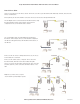
Cooper Bussmann BU-245U-E Wireless Ethernet & Device Server User Manual Access Point vs. Client The Access Point unit acts as the “wireless master” unit. The Access Point accepts and authorizes links initiated by client units, and controls the wireless communications. Clients (Stations) are slave units and when connected to the Access Point becomes transparent Ethernet link. The first diagram shows a connection between two Ethernet devices using BU-245U-E Ethernet modems.
Cooper Bussmann BU-245U-E Wireless Ethernet & Device Server User Manual Bridge vs. Router Each BU-245U-E is configured with an IP address for the Ethernet side, and another for the wireless side. A Bridge connects devices within the same Ethernet network - for example, extending an existing Ethernet LAN. For a Bridge, the IP address for the wireless side is the same as the Ethernet side. A Router connects devices on different LAN’s. The IP addresses for the Ethernet and wireless sides are different.
Cooper Bussmann BU-245U-E Wireless Ethernet & Device Server User Manual 1.2 Getting Started Quickly Most applications for the BU-245U-E require little configuration. The BU-245U-E has many sophisticated features, however if you don’t require these features, this section will allow you to configure the units quickly. First, read Chapter 2, “Installation.” The BU-245U-E requires an antenna and a power supply.
Cooper Bussmann BU-245U-E Wireless Ethernet & Device Server User Manual CHAPTER 2 INSTALLATION 2.0 General The BU-245U-E modules are housed in a rugged aluminum case, suitable for DIN-rail mounting. Terminals will accept wires up to 2.5 mm2 (12 gauge) in size. All connections to the module must be SELV (Safety Extra Low Voltage). Normal 110-250V mains supply must not be connected to any terminal of the BU-245U-E module. Refer to Section 2.3 Power Supply.
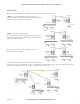
Cooper Bussmann BU-245U-E Wireless Ethernet & Device Server User Manual Dual Antenna Installations Most installations in industrial plants and factories use single omni-directional antennas. Installations can suffer from “ multi-path fading” effects where multiple reflected radio signals adversely affect the signal strength. This can be checked by moving the antenna a short distance (10 cm or 4 inches) - if the signal increases significantly then there are multi-path effects.
Cooper Bussmann BU-245U-E Wireless Ethernet & Device Server User Manual Installation tips Connections between the antenna and coaxial cable should be carefully taped to prevent ingress of moisture. Moisture ingress in the coaxial cable is a common cause for problems with radio systems, as it greatly increases the radio losses.
Cooper Bussmann BU-245U-E Wireless Ethernet & Device Server User Manual Directional Antennas. Directional antennas can be a: • Yagi antenna with a main beam and orthogonal elements, or • Directional radome, which is cylindrical in shape, or • Parabolic antenna. A directional antenna provides high gain in the forward direction, but lower gain in other directions. This may be used to compensate for coaxial cable loss for installations with marginal radio path.
Cooper Bussmann BU-245U-E Wireless Ethernet & Device Server User Manual 2.3 Serial Connections RS232 Serial Port The serial port is a 9 pin DB9 female and provides for connection to a host device as well as a PC terminal for configuration, field testing and for factory testing. Communication is via standard RS232 signals. The BU-245U-E is configured as DCE equipment with the pinouts detailed below. Hardware handshaking using the CTS/RTS lines is provided.
Cooper Bussmann BU-245U-E Wireless Ethernet & Device Server User Manual Shorter runs of 485 cable may not require the termination resistors to be enabled. 2.4 Discrete (Digital) Input/Output The BU-245U-E has one on-board discrete/digital I/O channel. This channel can act as either a discrete input or discrete output. It can be monitored, or set remotely, or alternatively used to output a communications alarm status.
Cooper Bussmann BU-245U-E Wireless Ethernet & Device Server User Manual CHAPTER 3 OPERATION 3.0 Start-up “Access Point” Start-up (BU-245U-E-G) When an Access Point (AP) unit starts up it checks to see if the Channel selection is set to “Auto” and if so will scan all available channels, pick the quietest then begin transmitting periodic messages, called beacons, if it is configured with a fixed channel it will immediately begins sending beacons, on the configured channel.
Cooper Bussmann BU-245U-E Wireless Ethernet & Device Server User Manual Roaming Clients Clients can roam within a system however if the link to the Access Point fails or the radio signal level becomes too weak it will scan for beacons and connect to an Access Point (provided the SSID and any Encryption methods, keys, etc are compatible). If there are multiple Access Points it will select the connection with the best signal level.
Cooper Bussmann BU-245U-E Wireless Ethernet & Device Server User Manual The 10M channels are also separated by 5MHz and overlap the adjacent channels by 5MHz forward and backward, i.e., Channel 41 will overlap with channel 42; channel 46 will overlap with channel 45 and 47. Lastly the 5MHz channels are separated by 5MHz and do not overlap at all so you can operate all 13 channels at the same time with minimal interference with the adjacent channel.
Cooper Bussmann BU-245U-E Wireless Ethernet & Device Server User Manual 802.11a (5GHz) The BU-245U-E-A utilizes frequency bands within the range of 5.15GHz and 5.825GHz. This is broken into 4 distinct U-NII bands and each region (EU, US, AUS, NZ, etc) have their own power and operational constraints, see Appendix C for more details. The example below shows the US power and operational constraints “Group 1”: 5.15-5.25GHz @ 50mW “Group 2”: 5.25-5.35GHz @ 250mW to 1 Watt “Group 3”: 5.47-5.
Cooper Bussmann BU-245U-E Wireless Ethernet & Device Server User Manual 3.2 Configuring the Unit for the First Time The BU-245U-E has a built-in web server, containing web pages for analyzing and modifying the module’s configuration. The configuration can be accessed using Microsoft® Internet Explorer version 7 or greater. This program is shipped with Microsoft Windows or may be obtained freely via the Microsoft® website. If using other browsers they must be fully compliant with IE7 SSL security.
Cooper Bussmann BU-245U-E Wireless Ethernet & Device Server User Manual Method 1 - Set PC to same network as BU-245U-E Connect the Ethernet cable between unit and the PC configuring the module. • Set the Factory Default Switch to the SETUP position. This will always start the BU-245U-E with Ethernet IP address 192.168.0.1XX, subnet mask 255.255.255.0, gateway IP 192.168.0.1 and the radio disabled.
Cooper Bussmann BU-245U-E Wireless Ethernet & Device Server User Manual To resume normal configured operation when Configuration is complete, switch Factory Default dip-switch on the BU-245U-E to RUN and cycle power. Note: Security Certificates. Configuration of the BU-245U-E uses an encrypted link (https). The security certificate used by the BU-245U-E is issued by Cooper Bussmann and matches the IP address 192.168.0.100.
Cooper Bussmann BU-245U-E Wireless Ethernet & Device Server User Manual • Open Internet Explorer and ensure that settings will allow you to connect to the IP address selected. If the PC uses a proxy server, ensure that Internet Explorer will bypass the Proxy Server for local addresses. This option may be modified by opening Tools -> Internet Options -> Connections Tab -> LAN Settings->Proxy Server -> bypass proxy for local addresses.
Cooper Bussmann BU-245U-E Wireless Ethernet & Device Server User Manual 3.4 Network Configuration You can view or modify Ethernet network parameters by selecting the “Network” menu. When prompted for username and password, enter “user” as the username, and “user” as the password in the password field (This is the factory default – See section 3.21 “Module Information Configuration” to change).
Cooper Bussmann BU-245U-E Wireless Ethernet & Device Server User Manual Network Settings Webpage Fields 26 Operating Mode Used to select Access Point (Infrastructure), Client (Infrastructure). By default this is set to Client. Device Mode Used to select Bridge or Router mode. By default this is set to Bridge. Bridge STP Checking this box enables Spanning Tree protocol in bridged networks. See to section 3.
Cooper Bussmann BU-245U-E Wireless Ethernet & Device Server User Manual 3.5 Security Menu Select the Radio Encryption level from the drop down menu on the Main index page and then press the “Save Changes” button. Available encryption levels are - “None”, “WEP (64-bit)”, “WEP (128-bit)”, “WPA PSK (TKIP)”, “WPA PSK (AES)”, “WPA2 PSK (AES)”, “WPA PSK/ WPA2 PSK” & WPA-Enterprise. The default setting is “None.
Cooper Bussmann BU-245U-E Wireless Ethernet & Device Server User Manual When WPA Encryption is selected, 128bit Encryption keys are internally generated based on the Passphrase and System Address (ESSID). The Passphrase must be between 8 and 63 characters in length, and the Passphrase must be the same for all BU-245U-E units in the same system. For optimal security a passphrase consisting of a combination of letters and numbers (i.e., not just a simple word or phrase) as well as upper and lower case. E.g.
Cooper Bussmann BU-245U-E Wireless Ethernet & Device Server User Manual 3.6 Normal Operation After addresses are configured, the units are ready for operation. Refer to section 1 for an explanation on the operation of a Bridge and Router. Transparent Bridge Operation A bridge connects several Ethernet networks together, and makes them appear as a single Ethernet network to higher protocol layers. By default, the BU-245U-E is configured as a transparent bridge.
Cooper Bussmann BU-245U-E Wireless Ethernet & Device Server User Manual Radio Mode BU-245U-E -G support 802.11b and 802.11g radio standards and to limit operation to one or the other, select the desired standard. Normally selecting “auto” allows the modem to make the best choice. BU-245U-E -A only supports 802.11a radio standard. Transmit Power Level This allows adjustment of the radio power.
Cooper Bussmann BU-245U-E Wireless Ethernet & Device Server User Manual Channel Selection BU-245U-E-G modem (2.4GHz 802.11b/g) channel selection is done by selecting one of 13 channels from the drop down “Channel” list. (Country Dependent) BU-245U-E-A modem (5GHz 802.11a) channel selection is shown below. You can select an individual channel from the list keeping in mind that the channel will have some transmit and/or DFS constraints as indicated in Section 3.1 “Selecting a Channel” and Appendix C.
Cooper Bussmann BU-245U-E Wireless Ethernet & Device Server User Manual Throughput and Repeaters It should also be noted that if using repeaters to extend the range there will be a reduction in throughput for each repeater hop. The following table shows the drop in throughput for each hop and for each of the channel widths. Data Throughput based on Repeater Hops 20MHz Channel Signal 10MHz Channel 5MHz Channel Rep Hops 1 2 3 4 1 2 3 4 1 2 3 4 -74dBm 22 11.0 5.5 2.8 11.0 5.5 2.8 1.
Cooper Bussmann BU-245U-E Wireless Ethernet & Device Server User Manual TX Antenna Select which antenna port the module will transmit from. Selections are Main Port Only, Both (Diversity) or Auxiliary Port Only. Module does not transmit from both ports at the same time. If needed, i.e., broadcast messages the radio will toggle transmissions between the antenna ports.
Cooper Bussmann BU-245U-E Wireless Ethernet & Device Server User Manual 3.10 DHCP Server Configuration The BU-245U-E is able to act as a DHCP server, supplying IP addresses automatically to other DHCP Client devices. Note that the BU-245U-E units need to act in conjunction with their connected devices. If a connected device is a DHCP server, the local and remote BU-245U-E units can be configured as DHCP Clients and receive IP addresses from the server device.
Cooper Bussmann BU-245U-E Wireless Ethernet & Device Server User Manual 3.12 Spanning Tree Algorithm The bridge “Spanning Tree Protocol” function was introduced to handle network loops and provide redundant paths in networks. To enable tick the STP box on any “WDS Connections” you have configured on the “Repeaters” configuration page. For example, consider this network with a redundant wireless link.
Cooper Bussmann BU-245U-E Wireless Ethernet & Device Server User Manual 3.13 Compatibility 3 Address (Layer 3 Bridge) & 4 Address Mode What Addresses are in a wireless Ethernet data frame? There are two different Wi-Fi communication “modes”, 3 Address and 4 Address Modes. Each mode has a slightly different way that it addresses the data frames to other devices on the network.
Cooper Bussmann BU-245U-E Wireless Ethernet & Device Server User Manual 240U-E Compatibility BU-245U-E-G modules can communicate with Cooper Bussmann 240U-E Ethernet modems however only in certain modes. The following table shows compatible configurations. If communicating with Cooper Bussmann 240U-E Ethernet modems the 240U-Es need to be configured with WDS (4 address mode), not the default “3-address mode” and the 240U-E APs cannot be auto connect to any WDS AP.
Cooper Bussmann BU-245U-E Wireless Ethernet & Device Server User Manual WDS bridge interfaces have the advantage that redundant paths are permitted when using the bridge Spanning Tree Protocol (see section 3.11 “Spanning Tree Algorithm”), thus behaving as a self-healing mesh network. Bridged networks are also not as configuration intensive as routed networks. Since WDS bridge interfaces generally do not require IP address configuration (they inherit the IP address of the standard wireless interface).
Cooper Bussmann BU-245U-E Wireless Ethernet & Device Server User Manual Example – Extending Range Using WDS One of the most common uses for WDS is to extend the range of the wireless network using repeaters. The diagram above illustrates a simple example where the four Access Points are all at fixed locations (each of the Access Points could, of course, have one or more client/stations connected).
Cooper Bussmann BU-245U-E Wireless Ethernet & Device Server User Manual Example - Roaming with WDS Access Points Another common use for WDS is extending the range across a large wireless network but allowing roaming connections between access points or being able to switch to the next Access Point when out of range of the previous Access Point.
Cooper Bussmann BU-245U-E Wireless Ethernet & Device Server User Manual Example – Adding Redundancy In the example below, 4 x Access Points (A, B, C, & D) form a mesh network using only WDS bridge interfaces. Each of the Access Points may also have its own clients associated. Each Access Point is configured with a different SSID, meaning the clients associated with each Access Point are fixed.
Cooper Bussmann BU-245U-E Wireless Ethernet & Device Server User Manual The configuration for Site A and B are shown below. In this example, Site B uses its primary access point to act as an access point for Virtual Stations on Site A and D, and uses a Virtual Station to act as a client to Site C. Site A uses two Virtual Stations to act as clients to Site B and to Site C.
Cooper Bussmann BU-245U-E Wireless Ethernet & Device Server User Manual Example – WDS Routed Network An example of using WDS router interfaces to achieve a similar physical topology to the WDS bridge example discussed earlier is illustrated below. In both examples, there are four WDS Access points each with the possibility of having their own client/stations associated. In both examples A, B, C, and D can all exchange data with each other.
Cooper Bussmann BU-245U-E Wireless Ethernet & Device Server User Manual So, in this example, Site B has a total of three IP addresses: 192.168.5.3 for the default interface; 169.254.0.3 for the WDS link to Site A; and 169.254.5.3 for the WDS link to Site C. Note: We choose to always use the same host address of 3 for unit B on all of its interfaces regardless of the network address. • The first routing rule specifies 192.168.0.
Cooper Bussmann BU-245U-E Wireless Ethernet & Device Server User Manual 3.15 Routing Rules When a BU-245U-E receives an IP frame that is destined for an IP address on a different network, it checks if the network address matches the network address of one of its own interfaces (i.e., hard-wired Ethernet, or wireless Ethernet, or WDS) and forwards the frame appropriately.
Cooper Bussmann BU-245U-E Wireless Ethernet & Device Server User Manual The Routing Rules configuration page can be accessed by selecting the “Routing” link on any of the configuration web pages. Up to 30 routing rules may be added to each BU-245U-E. The table below summarizes the configurable parameters of a routing rule. Name A name to describe the routing rule (Max 32 characters). Destination The destination network (or host) IP address (to specify a network address set the host address to 0. I.e.
Cooper Bussmann BU-245U-E Wireless Ethernet & Device Server User Manual • The IP Address filter checks both the source address and the destination address of the message. If either address match, then the rule is activated. • ARP filtering applies only to ARP request packets (typically these are broadcast packets) which are sourced from the Ethernet interface and destined for the wireless interface. (ARP requests from devices on the wireless network will always be passed to the Ethernet interface.
Cooper Bussmann BU-245U-E Wireless Ethernet & Device Server User Manual Select “Blacklist” or “Whitelist” Blacklist will prevent all listed devices from accessing the module and using the radio link. Whitelist will allow devices with the MAC addresses listed to communicate with the module and utilize the radio link. All other devices are blocked. Add Entry Add a row to the table of Mac Address filter rules Delete Entry Delete the currently selected MAC address filter rule.
Cooper Bussmann BU-245U-E Wireless Ethernet & Device Server User Manual ARP Filter Configuration ARP (Address Resolution Protocol) is a broadcast message and is primarily used for finding a MAC address when only its IP or some other Network Layer address is known. On large networks, you generally tend to get a high proportion of broadcast messages.
Cooper Bussmann BU-245U-E Wireless Ethernet & Device Server User Manual To configure Windows XP to establish a PPP connection to a BU-245U-E in SETUP mode, follow these steps: 1. On Network Connections in Windows XP, select Create a new connection. 2. On the New Connection Wizard, click Next. 3. Set up an advanced connection. 4. Connect directly to another computer. 5. Set PC as guest. 6. Set Connection Name. 7. Select a COM port. 8. Select availability. 9. Click Finish. 10.
Cooper Bussmann BU-245U-E Wireless Ethernet & Device Server User Manual Some of the possible Serial Gateway topologies are illustrated below. There are software packages available (i.e., SerialIP Redirector by Tactical Software) that can create a virtual serial port on a PC. This virtual serial port can be configured to connect to a BU-245U-E serial port. Standard programs can then be used to access this serial port as if it were actually connected to the PC.
Cooper Bussmann BU-245U-E Wireless Ethernet & Device Server User Manual 3.18 Serial Menu RS232 / RS485 Serial Port Configuration RS232 Port Select the desired functionality. Select either PPP, Serial Gateway or Modbus TCP to RTU Data Rate The serial data rate desired. Serial data rates available range from 110bps to a maximum of 115,200bps. Data Format The data format desired. All the standard data formats are supported.
Cooper Bussmann BU-245U-E Wireless Ethernet & Device Server User Manual RS232 / RS485 Serial Gateway Serial Gateway Mode Server - Module will wait for a connection to be initiated by a remote Client. Client - Module will automatically attempt to connect to the specified remote server. Multicast - Allows point to multi-point serial transfer. All members of the group will receive serial transmissions made by any other member of the Multicast group.
Cooper Bussmann BU-245U-E Wireless Ethernet & Device Server User Manual 3.19 Multicast Pipe Manager Previously it has been difficult to connect a single TCP device, i.e., a Scada / DCS system to multiple remote multicast serial devices. Multicast Pipe allows this type of connection. An example would be a Scada system that needs to communicate with multiple remote serial devices. A modem can be placed at each remote location and connected serially to each device.
Cooper Bussmann BU-245U-E Wireless Ethernet & Device Server User Manual 3.20 Digital Input/Output The functionality of the shared Digital Input/Output pin may be configured via the “I/O Transfer” webpage. As this pin is shared, the Digital Input status will be ON when the Digital Output is set ON. The Digital I/O channel can be transferred to/from another device using Modbus (see section “3.15 Modbus I/O Transfer”) or it can be configured to provide status of the module communications.
Cooper Bussmann BU-245U-E Wireless Ethernet & Device Server User Manual All Modbus Master messages are directed to/from the onboard I/O registers depending on configuration (described below). The Modbus TCP Client may also poll Modbus RTU (i.e., serial) devices connected to either the local serial port or a remote BU-245U-E serial port by enabling the Modbus TCP to RTU gateway at the corresponding serial port (see section 3.16 “Serial Port Configuration”).
Cooper Bussmann BU-245U-E Wireless Ethernet & Device Server User Manual • The first will write the register 4300 (Local Digital Input) to server IP address 192.168.0.200 (Unit B), Device ID #1, register 4320 (Local Digital output). • The second mapping shows a Modbus read command of 8 Discretes starting at register 1 (Destination Reg) on Device ID #6 connected to IP address 192.168.0.123 (it self) and store the values at register #1 locally.
Cooper Bussmann BU-245U-E Wireless Ethernet & Device Server User Manual Modbus TCP Client Mappings on I/O Transfer Menu: Local Register Enter the starting onboard I/O register number that the specified Modbus Master transaction will transfer I/O to/from. I/O Count Specify the number of consecutive I/O register to be transferred for the specified transaction. Function Code Specify the Modbus Function Code for the transaction.
Cooper Bussmann BU-245U-E Wireless Ethernet & Device Server User Manual 3.23 System Tools The System Tools Page has a number of tools that help maintain the module firmware and configuration. TCP Throughput Test Performs a Throughput Test. See section 3.23 ”TCP Throughput Test” below for details Configuration Summary This option is used to save all the different configuration pages onto one page, for easy viewing.
Cooper Bussmann BU-245U-E Wireless Ethernet & Device Server User Manual Connect to the web page of the module that will be performing the Iperf test, select “System Tools” link on the right hand side of the webpage and then select “TCP Throughput Test” and you will see the Screen as shown below. Note: TCP Throughput test must be run using Microsoft Internet Explorer 8 or later. Enter the IP address of the remote device that you wish to test and press the “Measure Throughput” button.
Cooper Bussmann BU-245U-E Wireless Ethernet & Device Server User Manual 3.25 Remote Configuration Because a module configuration is viewed and changed in a web format (which uses TCP/IP protocol), you can view or change the configuration of a remote module via the wireless link, provided the remote module already have a wireless link established to the local BU-245U-E.
Cooper Bussmann BU-245U-E Wireless Ethernet & Device Server User Manual Extending a Wired Network Access Point Configuration Connect straight through Ethernet cable between PC and BU-245U-E. Ensure configuration PC and BU-245U-E are setup to communicate on the same network Set dipswitch to SETUP mode. Power up unit, and wait for the OK LED to cease flashing. Adjust PC network settings Set Configuration PC network card with network setting of IP address 192.168.0.1, netmask 255.255.255.
Cooper Bussmann BU-245U-E Wireless Ethernet & Device Server User Manual Connecting two Separate Networks Together LAN A Configuration In this example, LAN A is connected to the internet via a router at IP address 192.168.0.1. Devices on LAN A that only require access to devices on LAN A and B, should have their gateway IP address set to the BU-245U-E Access Point as 192.168.0.200. Devices on LAN A, that must interact with devices on LAN A and B and the internet should set the internet router 192.168.0.
Cooper Bussmann BU-245U-E Wireless Ethernet & Device Server User Manual Client Configuration Perform the same configuration steps as the Access Point configuration with the following differences: Enter “Network”, and select Operating Mode as Client. Device Mode should be set to Bridge. Set the Gateway IP address to 169.254.102.54 Set the Ethernet IP address to 169.254.102.53, network mask 255.255.255.0 Set the Wireless IP address to 169.254.102.53, network mask 255.255.255.
Cooper Bussmann BU-245U-E Wireless Ethernet & Device Server User Manual CHAPTER 4 DIAGNOSTICS 4.0 Diagnostics Chart LED Indicator Condition Meaning OK GREEN Normal Operation OK RED Continuously Supply voltage too low.
Cooper Bussmann BU-245U-E Wireless Ethernet & Device Server User Manual 4.1 Diagnostic Information Available Connectivity The Connectivity webpage displays connections and available networks. The “Connected Devices” section displays the radio channel, received signal strength, and radio data rate for each Client or Access Point by their MAC Address. The readings shown are based upon the last received data message from the Access Point or Client.
Cooper Bussmann BU-245U-E Wireless Ethernet & Device Server User Manual 4.2 Channel Survey The Cooper bussmann 802.11 Ethernet modem utilizes a half duplex radio channel for communications. At any given time, an Access Point and its associated clients occupy a radio channel. These radio channels, or frequencies, are license free and may contain interference from any number of other radio transmitters.
Cooper Bussmann BU-245U-E Wireless Ethernet & Device Server User Manual The third screen shot shows the average Channel utilization for each minute up to one hour. It will also give a running average for the total number of minutes up to 59 minutes. The next screen shot shows the running radio receive noise floor average for each minute up to 59 minutes.
Cooper Bussmann BU-245U-E Wireless Ethernet & Device Server User Manual 4.3 Custom Survey Custom Survey is essentially the same as the Channel Survey (explained in the previous section) except the three channel utilizations can be turned on or off thus showing the different amount of traffic related data. Percent Radio TX – Any transmitted messages from the radio to other devices.
Cooper Bussmann BU-245U-E Wireless Ethernet & Device Server User Manual With this sort of outside interference it is recommended to perform the same test but over a longer period so as to get a clearer indication of channel utilization. 4.4 Statistics The Statistics webpage is used for advanced debugging of BU-245U-E. This webpage details the state of the BU-245U-E and performance information.
Cooper Bussmann BU-245U-E Wireless Ethernet & Device Server User Manual 4.5 Internal Diagnostics Modbus Registers There are a number of internal diagnostic registers that can be accessed via Modbus TCP/RTU that will help with analyzing and diagnosing the radio network. To access these register the Modbus Server will need to be enabled and a Modbus Server address will need to be configured (See 3.20 “Modbus I/O Transfer” for details on how this is done).
Cooper Bussmann BU-245U-E Wireless Ethernet & Device Server User Manual 72 Statistic Register Module Description 4500 Both Total data packets received on the interface 4502 Both Received frames with antenna 1 (TX/RX) 4504 Both Received frames with antenna 2 (RX) 4506 Both Receiver / default antenna switches 4508 Both Receive message failed due to bad CRC 4510 Both Receive message failed due to decryption 4512 Both Receive message failed due to MIC failure 4514 Both Receive messag
Cooper Bussmann BU-245U-E Wireless Ethernet & Device Server User Manual 4.6 Testing Radio Paths Connection and Signal Strength The general procedure for radio range testing a link is fairly simple. Configure two units to form a link using automatic radio rates. Install the Access Point at a fixed location. Take a laptop computer and the Client to each of the remote locations, and analyze the link using the Connectivity webpage.
Cooper Bussmann BU-245U-E Wireless Ethernet & Device Server User Manual 4.7 Utilities “Ping” Ping is a basic Internet program that lets you verify that a particular IP address exists and can accept requests. Ping is used diagnostically to ensure that a host computer or device you are trying to reach is actually operating. If, for example, a user can’t ping a host, then the user will be unable to send files to that host.
Cooper Bussmann BU-245U-E Wireless Ethernet & Device Server User Manual ”Ipconfig” “ipconfig” can be used to show your current TCP/IP information, including your address, DNS server addresses, adapter type and so on. In the above example ipconfig was entered in the command prompt. The reply back shows the PC’s IP address, Subnet mask and the gateway it is connected to. Other ipconfig commands will return back more information.
Cooper Bussmann BU-245U-E Wireless Ethernet & Device Server User Manual ”Route” Route is used for the Router function. This is where you are joining 2 different networks together via the BU-245U-E refer to Section 1.1 Normally the BU-245U-E will only accept one routing rule, by using the Default Gateway IP Address on the Main Network Page. If more than one routing rule is needed then a Routing Table is required, e.g. Multiple networks each with a different IP range.
Cooper Bussmann BU-245U-E Wireless Ethernet & Device Server User Manual CHAPTER 5 SPECIFICATIONS General EMC specification Radio specification Housing Terminal blocks LED indication Operating Temperature EN 300 683 EN 300 328 114 x 140 x 30mm, 4.5 x 5.5 x 1.2 inch Removable Module Status, Serial RX and TX, Radio RX and TX, Radio Link, Ethernet Activity / Link -40 to +60°C, -40 to +140°F FCC Part 90 FCC Part 15.247, RSS 210 Powder-coated, extruded aluminum, DIN rail mount Suitable for 12 gauge (2.
Cooper Bussmann BU-245U-E Wireless Ethernet & Device Server User Manual Serial Ports RS232 Port RS485 Port Data rate (bit/sec) configurable DB9 female DCE 2 pin terminal block 1200, 2400, 4800, 9600, 14400, 19200, 38400, 57600, 76800, 115200 RTS/CTS/DTR/DCD hardware signals provided Max distance 4000’ / 1.
Cooper Bussmann BU-245U-E Wireless Ethernet & Device Server User Manual APPENDIX A FIRMWARE UPGRADE Determine which firmware version is present in the module to be upgraded by viewing the index webpage of the module. Firmware versions 1.0.3 and later may be upgraded via the configuration web pages. This upgrade can be done locally with a PC connected directly to the module, or remotely over a working radio link.
Cooper Bussmann BU-245U-E Wireless Ethernet & Device Server User Manual APPENDIX B GLOSSARY ACK Acknowledgment. Access Point An access point connects wireless network stations (or clients) to other stations within the wireless network and also can serve as the point of interconnection between the wireless network and a wired network. Each access point can serve multiple users within a defined network area. Also known as a base station.
Cooper Bussmann BU-245U-E Wireless Ethernet & Device Server User Manual Encryption Key An alphanumeric (letters and/or numbers) series that enables data to be encrypted and then decrypted so it can be safely shared among members of a network. WEP uses an encryption key that automatically encrypts outgoing wireless data. On the receiving side, the same encryption key enables the computer to automatically decrypt the information so it can be read.
Cooper Bussmann BU-245U-E Wireless Ethernet & Device Server User Manual Receive Sensitivity The minimum signal strength required to pick up a signal. Higher bandwidth connections usually have less receive sensitivity than lower bandwidth connections. RJ-45 Standard connectors used in Ethernet networks. RJ-45 connectors are similar to standard RJ-11 telephone connectors, but RJ-45 connectors can have up to eight wires, whereas telephone connectors have four.
Cooper Bussmann BU-245U-E Wireless Ethernet & Device Server User Manual TCP/IP The underlying technology behind the Internet and communications between computers in a network. The first part, TCP, is the transport part, which matches the size of the messages on either end and guarantees that the correct message has been received. The IP part is the user's computer address on a network.
Cooper Bussmann BU-245U-E Wireless Ethernet & Device Server User Manual APPENDIX C CHANNELS 802.
Cooper Bussmann BU-245U-E Wireless Ethernet & Device Server User Manual 802.
Cooper Bussmann BU-245U-E Wireless Ethernet & Device Server User Manual APPENDIX D 802.
Cooper Bussmann BU-245U-E Wireless Ethernet & Device Server User Manual APPENDIX E EXTERNAL IPERF TEST This Appendix shows how to set up and use the Iperf application to test the throughput of Ethernet Modems. Iperf is a tool used to measure the throughput and quality of a network link. Jperf is used in conjunction with Iperf and displays the Iperf data results graphically. This instruction covers both Iperf and Jperf, it does not cover the setup and configuration of the modems.
Cooper Bussmann BU-245U-E Wireless Ethernet & Device Server User Manual This time enter the Iperf command to start the client communication to the server. “Iperf –c -w 65535. See Figure 2 Figure 2 This will run a test over the Wi-Fi Link to the Server PC and report back results as seen in Figure 3. These results show the Bandwidth (Throughput) of the test as 16.2Mbits/sec.
Cooper Bussmann BU-245U-E Wireless Ethernet & Device Server User Manual JPerf Application Jperf is a graphical interface that runs over the top of Iperf. It will display a graph result from the Iperf test. To run Jperf open a CMD prompt and change to the “jperf-2.0.2: directory and run the “Jperf” application as shown in Figure 4. The CMD screen will disappear and the Jperf Screen will appear as seen in Figure 5.
Cooper Bussmann BU-245U-E Wireless Ethernet & Device Server User Manual APPENDIX F GNU FREE DOC LICENSE Version 2, June 1991 Copyright (C) 1989, 1991 Free Software Foundation, Inc. 51 Franklin Street, Fifth Floor, Boston, MA 02110-1301, USA Everyone is permitted to copy and distribute verbatim copies of this license document, but changing it is not allowed. Preamble The licenses for most software are designed to take away your freedom to share and change it.
Cooper Bussmann BU-245U-E Wireless Ethernet & Device Server User Manual 2. You may modify your copy or copies of the Program or any portion of it, thus forming a work based on the Program, and copy and distribute such modifications or work under the terms of Section 1 above, provided that you also meet all of these conditions: a) You must cause the modified files to carry prominent notices stating that you changed the files and the date of any change.
Cooper Bussmann BU-245U-E Wireless Ethernet & Device Server User Manual 6. Each time you redistribute the Program (or any work based on the Program), the recipient automatically receives a license from the original licensor to copy, distribute or modify the Program subject to these terms and conditions. You may not impose any further restrictions on the recipients' exercise of the rights granted herein. You are not responsible for enforcing compliance by third parties to this License. 7.
Cooper Bussmann BU-245U-E Wireless Ethernet & Device Server User Manual 3A1576Rev1.6 www.cooperbussmann.
Customer Assistance Customer Satisfaction Team Application Engineering Available to answer questions regarding Cooper Bussmann products & services Monday-Friday, 8:00 a.m. – 4:30 p.m. for all US time zones. Contact: s Toll-free phone: 855-287-7626 (855-BUSSMANN) s Toll-free fax: 800-544-2570 s E-mail: busscustsat@cooperindustries.com Technical assistance is available to all customers. Staffed by degreed engineers, this application support is available Monday-Friday, 8:00 a.m. – 5:00 p.m.