
Installation guide

10
www.cooperbussmann.com/BussmannWirelessResources
Cooper Bussmann BU-905U-L Wireless I/O Configuration Manual
INTRODUCTION TO CONFIGURING YOUR UNIT
This section describes how to configure your BU-905U-L.
NOTE: For more information on installing your BU-905U-L, please see the BU-905U-L Installation Guide.
You can configure your network using:
• User-defined (customized) configuration – that lets you set specific information about your network and allows communication with other
Cooper Bussmann BU_905U-L modules.
• Default factory configuration – that lets you use a transmitter and receiver as a simple send/receive pair.
This manual describes how to perform custom configuration to:
• Fully utilize of the features of the BU-905U-L modules; and
• Communicate between BU-905U-L modules and other Cooper Bussmann BU_905U-L modules.
For more information on restoring the default configuration (i.e., linking), refer to the Quick Start Guide included with your module.
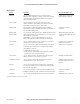
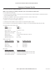
The following tables detail the default settings:
Setting
Default
Periodic transmission Every second
Analog sample rate 5 Samples per second
Analog change of state sensitivity 3%
Output state on comms failure Reset to zero
Analog setpoints Set by rotary switch (switch value x 10%±5%)
Analog Input debounce 1 Sample
Digital input debounce time 0.5 Seconds
Signals sent over radio
BU-905U-L-T(T
ransmitter) Sends BU-905U-L-R (Receiver)
Digital Input 1 Digital Output 1
Digital Input 2 Digital Output 2
Analog Setpoint
Digital Output 3
Analog Input (4-20mA)
Analog output
Other signals
BU-905U-L-T(T
ransmitter) BU-905U-L-R (Receiver)
Thermocouple Input (Not used) Communication Failure (All timeouts set to 10 seconds)
Setpoint Output (Local indication) Communication Failure (All timeouts set to 10 seconds)
System OK (On if system OK) System OK (On if system OK)
3A1579Rev1.4