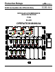
Protective Relays SALES AID M-LIB3 Low Impedance Bus Differential Relay S150-34-1 MODULAR LOW IMPEDANCE BUS PROTECTION TYPE M-LIB3 OPERATION MANUAL October 1999 1999 Cooper Industries, Inc. •New Issue.
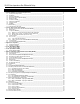
M-LIB3 Low Impedance Bus Differential Relay INDEX 1 General utilization and commissioning directions_______________________________________________________ 3 1.1 Storage and transportation______________________________________________________________________ 3 1.2 Installation___________________________________________________________________________________ 3 1.3 Electrical connection___________________________________________________________________________ 3 1.
S150-34-1 GENERAL UTILIZATION AND COMMISSIONING DIRECTIONS Always make reference to the specific description of the product and to the Manufacturer's instructions. Carefully observe the following warnings. 1.1 STORAGE AND TRANSPORTATION Must comply with the environmental conditions stated on the product's instruction or by the applicable IEC standards. 1.2 INSTALLATION, Must be properly made and in compliance with the operational ambient conditions stated by the Manufacturer. 1.
M-LIB3 Low Impedance Bus Differential Relay a. Before removing a module, ensure that you are at the same electrostatic potential as the equipment by touching the case. b. Handle the module by its front-plate, frame, or edges of the printed circuit board. Avoid touching the electronic components, printed circuit tracks or connectors. c. Do not pass the module to any person without first ensuring that you are both at the same electrostatic potential. Shaking hands achieves equipotential. d.
S150-34-1 GENERAL CHARACTERISTICS AND OPERATION 1.12 Modular Low Impedance Bus Bar Protection M-LIB3 The M-LIB system is constituted of a number of modular units, which can be combined to suit to any busbar configuration and allow for easy extension. 1.13 Main features q Low impedance and low burden on main CTS. q High stability with zone biased differential elements and CT saturation detectors. q High speed of operation.
M-LIB3 Low Impedance Bus Differential Relay 1.14.2 M-BC3 = Bus coupler / sectionalizer module (SCE1578) Including : q sets of three auxiliary CTs : 1 set for each side of the bus coupler. q 1 Bus coupler trip output. q 1 Bus Coupler trip input from Feeders’Breaker Failure Relays 1.14.3 M-LID3 = Numerical biased protection relay With the following features : 6 q Double circuit for Biased differential protection. q Double circuit for unbiased differential protection.
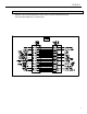
S150-34-1 2.4 F/C Rack Panel 19”3U rack panel suitable to house up to seven plug-in modules type M-BF3 or M-BC3 including back printed circuit board with : q Diodes for supply of the measurement bus of two Main Zones and one Check Zone q 7 Female sockets for plug-in connection of the M-BF3 or M-BC3 modules. q 7 Terminal boards with screw terminals for connection to the system. q 1 Male connector socket for interfacing with the differential protection relays.
M-LIB3 Low Impedance Bus Differential Relay 2.5 ACCESSORIES 2.5.1 CF1 – Cable with female plug Female connector plug with multicore cable for connection between the terminals of the protection relays and the Zone wiring bus.
S150-34-1 2.5.2 CFM – Interconnection cable with Male and Female plugs Multicore cable terminated with one male and one female connector plugs for interconnection between F/C Rack Panels.
M-LIB3 Low Impedance Bus Differential Relay 2.6 Technical Data q Standards: IEC 255, 1000, CE q Rated Frequency: 50/60 Hz q Rated input current: 1 A q Current overload: 2 In q Transient overload: 100 In q Setting ranges: • Fn = 50/60 Hz • Ids = zone differential current = (0,2-2) In • R = Bias per Unit = (0,4 - 1) p.u. • ISV = Circuit supervision current = (0,1 – 1) In • Operating time: ≤ 20 ms • Stability level: ≥ 40 In max. 2.
S150-34-1 3 APPARATUS CONFIGURATION The M-LIB3 modular protection apparatus is combined according to the configuration of the protected bus bar System. Generally the following components are needed : q One M-LID3 differential relay for each of the protected bus bar zone. q One M-LID3 differential relay for each Check Zone (normally one only). The M-LID3 relays can be supplied as individual flush mounting units or combined in 19”3U rack panel.
M-LIB3 Low Impedance Bus Differential Relay 3.
S150-34-1 3.
M-LIB3 Low Impedance Bus Differential Relay 14
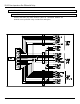
S150-34-1 4 FEEDER INPUT MODULE M-BF3 M-BF3 is a 51mm wide draw-out modular unit to be plug-in into the F/C rack panel that can house up to 7 modules M-BF3 or M-BC3. With reference to the block diagram SCE1577 the module M-BF3 receives the measuring input from the three Feeder’s Current transformers (eventually from the ratio adapting transformers) and the configuration input from the position signal contacts of the busbar selection isolators.
M-LIB3 Low Impedance Bus Differential Relay F/C PANEL M-BF3 CARD BACK SIDE Each of the 7 bays of the F/C panel can accept either one module M-BF3 or one module M-BC3 q q 16 Current input burden (each module) : In = 1A : 0.5 VA – 0.
S150-34-1 4.
M-LIB3 Low Impedance Bus Differential Relay 5 BUS COUPLER INPUT MODULE M-BC3 M-BC3 is a 51mm wide draw-out modular unit to be plug-in into the F/C rack panel that can house up to 7 modules M-BC3 or M-BF3. With reference to the block diagram SCE1578 the module M-BC3 receives the measuring input from the two sets of the Bus Coupler’s current transformer (eventually from the ratio adapting transformers).
S150-34-1 F/C PANEL M-BC3 CARD BACK SIDE Each of the 7 bays of the F/C panel can accept either one module M-BF3 or one module M-BC3 q Current input burden (each module) : In = 1A : 0.5 VA – 0.
M-LIB3 Low Impedance Bus Differential Relay 5.
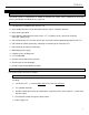
S150-34-1 6 M-LID3 DIGITAL LOW IMPEDANCE DIFFERENTIAL PROTECTION RELAY TYPE M-LID3 dA> dB> dC> PROG/ REMOTE TIME I.R.F. TRIGGER SYNC. MICROELETTRICA MILANO dsv BLOCK INPUT SCIENTIFICA ITALY MODE SELECT LOW IMPEDANCE BIASED DIFFERENTIAL RELAY TYPE M-LID3 + - PROG.
M-LIB3 Low Impedance Bus Differential Relay 6.1 GENERAL CHARACTERISTIC Currents from the CTs of the Feeders connected to each protected zone are conveyed to a wiring bus (one for each phase) that drives the positive and negative halfwave of the current on two different wires. The wiring bus also carries the signal from the CT’s saturation detectors.
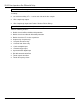
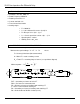
S150-34-1 The signal from CT saturation detectors shunts the measurement for a time proportional to the saturation. This strongly contributes to stability during through faults while maintaining high sensitivity to internal faults. The operation logic in each phase is functionally explained in the following diagram. Id1 A/D 1 1IR Id1>[ISV] x 0.9 Id Id1>[IdS] IR A/D 2 ZONE TRIP ENABLE & Id1>IS x 0.
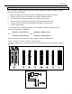
M-LIB3 Low Impedance Bus Differential Relay To compensate the differential current produced by CT’s error or saturation, the actual minimum operation level IS is dynamically adjusted in function of the actual through current IR according to the set coefficient [1R], [2R] Is/In „ ƒ [2R] ‚ ∆Ids ∆IR [Ids/In] • [1R] ∆Ids R= ∆IR ∆Ids IR/In [1IR] [2IR] • IR < [1IR] : IS = IdS ‚ [1IR] < IR < [2IR] : IS = IdS + 1R(IR-[1IR]) ƒ IR > [2IR] : IS = IdS + 1R([2IR]-[1IR]) + 2R(IR-[2IR]) „ BIAS SATU
S150-34-1 6.5 CONTROLS AND MEASUREMENTS Five key buttons allow for local management of all of the relay's functions. An 8-digit high brightness alphanumerical display shows the relevant readings (xxxxxxxx) (see synoptic table fig.1) FIG.1 MODE SELECT ACT MEAS MEASURES Measurements display + - ENTER Actual measuremant values MAX VAL Max.
M-LIB3 Low Impedance Bus Differential Relay 6.6 SIGNALIZATIONS Eight signal LEDs (normally off) are provided: a b c d dA> dB> dC> dvs PROG/ REMOTE TIME BLOCK I.R.F. TRIGGER SYNC. INPUT e a) Red LED dA> b) Red LED dB> c) Red LED dC> d) Red LED dvs e) Yellow LED PROG/ I.R.F. f) Red LED g) Red LED h) Yellow LED q q q q q q q q f g h Flashing when IdA > [Ids]. Illuminated on tripping of the biased differential element : IdA > IS Flashing when IdB > [Ids].
S150-34-1 6.7 OUTPUT RELAYS Five output relays are available (R1, R2, R3, R4, R5) q The relays R1,R2,R3,R4 are normally de-energized (energized on trip): these output relays are user programmable and any of they can be associated to any of the M-LID3's functions. Any relay associated to of any function picks-up as soon as the measured input value gets into the operation zone.
M-LIB3 Low Impedance Bus Differential Relay 6.11 TEST Besides the normal "WATCHDOG" and "POWERFAIL" functions, a comprehensive program of self-test and self-diagnostic provides : q Diagnostic and functional test with checking of program routines and memory's content, run every time the aux. power is switched-on: the display shows the type of relay and its version number and then switches over to the default display. q Dynamic functional test is run during normal operation every 10 minutes.
S150-34-1 6.13 READING OF MEASUREMENTS AND RECORDED PARAMETERS Enter the MODE "MEASURE", SELECT the menus "ACT.MEAS"-"MAX VAL"-"LASTTRIP""TRIP NUM", scroll available information by key "+" or "-" . 6.13.1 ACT.MEAS Actual values as measured during the normal operation. The values displayed are continuously updated. Display xxxxxxx xx:xx:xx dAxx.xxn dBxx.xxn dCxx.xxn IR xx.xn IS xx.xn Description Current date in the DDMMMYY format. Current time in the HH:MM:SS format. R.M.S.
M-LIB3 Low Impedance Bus Differential Relay 6.14 READING OF PROGRAMMED SETTINGS AND RELAY'S CONFIGURATION Enter the mode "SET DISP", select the menu "SETTINGS" or "F → RELAY", scroll information available in the menu by keys "+" or "-". SETTINGS= values of relay's operation parameters as programmed F → RELAY= output relays associated to the different functions as programmed. 6.15 PROGRAMMING The relay is supplied with the standard default programming used for factory test.
S150-34-1 6.15.2 PROGRAMMING THE CONFIGURATION OF OUTPUT RELAYS d> - 2 - 4 This is the name This dash means The number 2 of protective that output relay means that element number 1 is not output relay 2 assigned to this will operate when this element This dash The number 4 means that means that output output relay relay 4 will operate number 3 is not when this element trips assigned to this element Mode PROG menu F→ RELAY (Production standard settings here under shown).
M-LIB3 Low Impedance Bus Differential Relay 6.16 MANUAL AND AUTOMATIC TEST OPERATION 6.16.1 Mode "TESTPROG" subprogram “W/O TRIP" Operation of the yellow key activates a complete test of the electronics and the process routines. All the LEDs are lit-on and the display shows (TEST RUN). If the test routine is successfully completed the display switches-over to the default reading (dAxx.xxn). If an internal fault is detected, the display shows the fault identification code and the relay R5 is de-energized.
S150-34-1 6.18 CLOCK AND CALENDAR The unit features a built in clock calendar with Years, Months, Days, Hours, Minutes, Seconds, and Tenths of seconds and Hundredths of seconds. 6.18.1 Clock synchronization. The clock can be synchronized via a digital input (terminals 1 – 14) or the serial communication interface. The following synchronization periods can be set: 5, 10, 15, 30, 60 minutes.
M-LIB3 Low Impedance Bus Differential Relay 6.
S150-34-1 6.20 ELECTRICAL CHARACTERISTICS q REFERENCE STANDARDS q Dielectric test voltage IEC 60255-5 2kV, 50/60Hz, 1 min. q Impulse test voltage IEC 60255-5 5kV (c.m.), 2kV (d.m.
M-LIB3 Low Impedance Bus Differential Relay This page intentianally left blank.