
User Manual

Page 2
2 Mega Pixel IP Camera User Manual
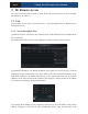
1.3 Overview
This series of cameras support varifocal lens and prime lens. If the camera you get is
prime lens, please skip the descriptions of the zoom and focus.
7
8
10
9
11
12
2
3
4
5
6
1
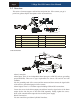
1
Network cable
7
Zoom
2
MIC IN cable
8
Focus
3
Headphone cable
9
Network indicator
4
Alarm input/output cable
10
Reset hole
5
RS485 cable
11
DC IN&CVBS port for testing
6
Power cable
12
TF card slot
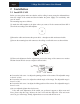
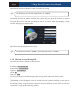
Cable Connections
N e twor k Ca ble
N
e
t
w
o
r
k
C
a
b
l
e
N e twor k Ca ble
N e twor k Ca ble
N
e
t
w
o
r
k
C
a
b
l
e
Internet
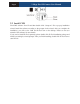
ALM-COM
ALM-NO
ALM-IN
ALM-GND
RS485T+
RS485T-
Alarm Connection:
Alarm Input: There is one independent alarm input port (ALM-IN) and one grounding
port(ALM-GND). There are no type requirements for sensors. NO and NC are both
available.
Join the grounding ends of the sensor and the camera and then connect the signal cable
of the sensor to the alarm input port of the camera.
Alarm Output: There is 1 CH alarm output including COM and NO connections.
Loosen the screws in the alarm output port and then insert the signal wires of the alarm
output devices into the port of NO and COM separately. Finally, tighten the screws.
Some of the external alarm output devices need the power supply.
RS 485 Connection:
You can control the speed dome by RS485 interfaces.