AURORAR10,000 COOLING UNIT Installation Manual Part No. 300381000 July 13, 1988 Revised: April 12, 1993 THIS DOCUMENT CONTAINS IMPORTANT INFORMATION This Manual must be read and understood before installing or operating this equipment Ó IMI CORNELIUS INC; 1988--93 PRINTED IN U.S.
TABLE OF CONTENTS Page GENERAL INFORMATION . . . . . . . . . . . . . . . . . . . . . . . . . . . . . . . . . . . . . . . . . . . . . . . . . . 1 GENERAL DESCRIPTION . . . . . . . . . . . . . . . . . . . . . . . . . . . . . . . . . . . . . . . . . . . . . . 1 COOLING UNIT DESCRIPTION . . . . . . . . . . . . . . . . . . . . . . . . . . . . . . . . . . . . . . . . . SYSTEM THEORY OF OPERATION . . . . . . . . . . . . . . . . . . . . . . . . . . . . . . . . . . . . . INSTALLATION . . . . . . . . . . . . . .
TABLE OF CONTENTS (cont’d) Page ADJUSTING DISPENSING VALVES WATER FLOW RATE . . . . . . . . . . . . . ADJUSTING WATER-TO-SYRUP ‘‘RATIO’’OF DISPENSED PRODUCT . 16 16 ADJUSTING SIZE OF DRINK DISPENSED . . . . . . . . . . . . . . . . . . . . . . . . . . . ADJUSTING CARBONATOR TANK LIQUID LEVEL . . . . . . . . . . . . . . . . . . . . REPLENISHING CO2 SUPPLY . . . . . . . . . . . . . . . . . . . . . . . . . . . . . . . . . . . . . . REPLENISHING SYRUP SUPPLY . . . . . . . . . . . . . . . . . . . . . . . . . .
TABLE OF CONTENTS (cont’d) Page TROUBLESHOOTING . . . . . . . . . . . . . . . . . . . . . . . . . . . . . . . . . . . . . . . . . . . . . . . . . . . . . . WATER-TO-SYRUP ‘‘RATIO’’OF DISPENSED DRINK TOO LOW OR TOO HIGH. . . . . . . . . . . . . . . . . . . . . . . . . . . . . . . . . . . . . . . . . . . . . . . . . . . . . . . . . . . . ADJUSTMENT OF DISPENSING VALVE SYRUP FLOW REGULATOR DOES NOT INCREASE TO DESIRED WATER-TO-SYRUP ‘‘RATIO” . . . . . . . . . . . . . . .
TABLE OF CONTENTS (cont’d) Page LIST OF FIGURES CONT’D) FIGURE 14. WIRING DIAGRAM (LOW-VOLTAGE SYSTEM) . . . . . . . . . . . . . . . . 36 FIGURE 15. WIRING DIAGRAM (HIGH-VOLTAGE SYSTEM) . . . . . . . . . . . . . . . 37 LIST OF TABLES TABLE 1. DESIGN DATA . . . . . . . . . . . . . . . . . . . . . . . . . . . . . . . . . . . . . . . . . . . . . . . TABLE 2. LOOSE-SHIPPED PARTS . . . . . . . . . . . . . . . . . . . . . . . . . . . . . . . . . . . . .
GENERAL INFORMATION IMPORTANT: To the user of this manual - This manual is a guide for installing, operating, and maintaining this equipment. Refer to Table of Contents for page location of detailed information pertaining to questions that arise during installation, operation, service and maintenance, or trouble-shooting this equipment.
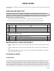
Table 1. Design Data COOLING UNIT MODEL NUMBERS: 60 HZ Unit: Standard Cooling Unit with Internal Condenser Coil and Fan Assembly Cooling Unit Requiring Connection to Remote Condenser Coil and Fan Assembly 50 HZ Unit: Standard Cooling Unit with Internal Condenser Coil and Fan Assembly 416593 416594 496593 COOLING UNIT DATA Overall Dimensions: Height Width Depth 28-inches 36-1/2 inches 24-1/2 inches NOTE: Overall dimensions if Cooling Unit is placed on optional Cooling Unit Stand (P/N 309309069).
Table 1. Design Data (cont’d) REMOTE CONDENSER COIL AND FAN ASS’Y DATA (P/N 309602000) Overall Dimensions: Height Width Depth Weight: Shipping 27 inches 22-inches 38-inches 85 pounds Ambient Operating Temp. Electrical Requirements: Operating Voltage -22°F to 158°F 208/230VAC, Single Phase, 60Hz 2.
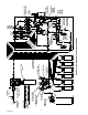
300381000 4 WATER PRESSURE REGULATOR CO2 CYLINDER PRIMARY CO2 REGULATOR GAS CHECK VALVE(2) CARBONATORS CO2 REGULATORS SUGAR SYRUP CO2 REGULATOR LINE LEGEND CO2 PLAIN WATER CARB WATER SYRUP PLAIN WATER SOURCE SHUTOFF VALVE CO2 GAS CHECK VALVE DOUBLE LIQUID CHECK VALVE(2) CARBONATED WATER CIRCULATING PUMP TEE FITTING FIGURE 2.
INSTALLATION This section covers unpacking and inspection, selecting location, installing Cooling Unit, preparing for operation, and operation. UNPACKING AND INSPECTION NOTE: The Cooling Unit was thoroughly inspected before leaving the factory and the carrier has accepted and signed for it. Any damage or irregularities should be noted at time of delivery (or not later than 15 days from date of delivery) and immediately reported to the delivering carrier.
fused as indicated on the Unit nameplate. The power circuit may also be wired through an equivalent HACR type circuit breaker rather then the disconnect switch.
CONNECTING REMOTE CONDENSER COIL AND FAN ASS’Y (IF APPLICABLE) REFRIGERATION LINES TO COOLING UNIT (see Figure 6 ) Connect refrigeration lines, from Remote Condenser Coil and Fan Assembly, to refrigeration connectors on back of Cooling Unit. CONNECTING ELECTRICAL POWER CIRCUIT TO COOLING UNIT (see Figures 5 or 6 and 15) IMPORTANT: Before applicable single-phase 60HZ or 50HZ electrical power circuit is connected to the Cooling Unit, service power voltage entering the building must be identified.
WARNING: The Cooling Unit must be electrically grounded to avoid possible fatal electrical shock or serious injury to the operator. A green ground wire is provided inside electrical box to connect power circuit ground wire which electrically grounds the Cooling Unit. 2.
D. Reinstall Cooling Unit electrical control box and secure with four screws. E. Install cover on electrical handy box on back of Cooling Unit. CONNECTING PLAIN WATER INLET SUPPLY LINE TO COOLING UNIT (see Figure 2) NOTE: IMI Cornelius Inc. recommends that a water shutoff valve be installed in plain water inlet supply line connected to Cooling Unit and that water supply be filtered.
CONNECTING COOLING UNIT SYRUP OUTLET LINES TO INSULATED PYTHON SYRUP LINES (see Figure 2) Connect Cooling Unit syrup outlet lines labeled No. 1 through No. 6, with barbed fittings on their ends, to insulated python lines labeled No. 1 through No. 6. Secure connections with TUBING CLAMPS (item 2).
3. Lower Cooling Unit into operating position to complete seal from unit base to floor. Apply additional sealant around bottom of base. Seal must have a minimum radius of 1/2-inch to prevent cracks and crevices and to ensure a complete seal. 4. Route Cooling Unit water tank overflow hose to permanent floor drain. 5. Seal area around overflow hose where they exit from unit using permagum sealant or equivalent. PREPARING COOLING UNIT FOR OPERATION 1.
STARTING COOLING UNIT REFRIGERATION SYSTEM NOTE: As ice bank forms in water tank, water expansion will take place and excess water will escape through water tank overflow hose to permanent floor drain. Cooling Unit Connected To Remote Condenser Coil and Fan Assembly. (P/N 309602000). Place Cooling Unit REFRIGERATION POWER switch in ‘‘ON’’(up) position. Refrigeration compressor, compressor cooling fan, agitator motor, and Remote Condenser Coil and Fan Assembly will start.
LEAK CHECK AND INSULATING COOLING UNIT OUTLET LINES 1. Check all CO2, plain and carbonated water, and syrup connections for leaks and repair if evident. 2. Make sure Cooling Unit outlet lines connections to insulated python lines are well insulated. 3. Install Cooling Unit top cover and secure with two screws. DISPENSING STATION ADJUSTMENTS ADJUSTING WATER FLOW RATE Refer to Installation Instructions provided with dispensing station for dispensing valve water flow rate adjustment instructions.
THIS PAGE LEFT BLANK INTENTIONALLY 300381000 14
OPERATORS INSTRUCTIONS This section covers operating controls, daily pre-operation check, adjustments, replenishing CO2 and syrup supplies, cleaning and sanitizing, Cooling Unit maintenance, Remote Condenser Coil and Fan Assembly (if applicable) maintenance, lubrication, and servicing CO2 gas check valves. WARNING: Disconnect electrical power to Cooling Unit to prevent personal injury before attempting any Cooling Unit or Rooftop Condenser Coil and Fan Assembly (if applicable) internal maintenance.
Cooling Unit Connected to Remote Condenser Coil and Fan Assembly. (see Figure 6) This Cooling Unit is equipped with a refrigeration system temperature sensing device and a high-pressure sensing cutout switch that will shut refrigeration system down should the system overheat due to a clogged condenser coil in the Remote Condenser Coil and Fan Assembly.
NOTE: When indicator on CO2 cylinder regulator assembly 1800-psi gage is in shaded (‘‘change CO2 cylinder’’) portion of the dial, CO2 cylinder is almost empty and should be changed. CO2 supply should be checked daily and if necessary, replenished as instructed. REPLENISHING SYRUP SUPPLY Syrup supply should be checked daily and if necessary, replenished as instructed.
COOLING UNIT CARBONATED WATER CIRCULATING PUMP MOTOR LUBRICATION Carbonated water circulating pump motor bearings must be oiled periodically as instructed. REMOTE CONDENSER COIL AND FAN ASS’Y (IF APPLICABLE) MAINTENANCE (see Figure 6) CAUTION: Remote Condenser Coil and Fan Assembly connected to this Cooling Unit is equipped with a condenser coil that must be cleaned every 30-days.
SERVICE AND MAINTENANCE This section describes Service and Maintenance procedures to be performed on the Cooling Unit and the Remote Condenser Coil and Fan Assembly. WARNING: Disconnect electrical power to Cooling Unit to prevent personal injury before attempting any Cooling Unit or Remote Rooftop Condenser Coil and Fan Assembly (if applicable) internal maintenance. Only qualified personnel should service internal components or electrical wiring.
COOLING UNIT MAINTENANCE PERIODIC CLEANING Periodically wash all external surfaces of Cooling Unit, rinse with clean water, then wipe dry with a clean soft cloth. DO NOT USE ABRASIVE TYPE CLEANERS. CLEANING CONDENSER COIL Cooling Unit Equipped With Condenser Coil and Air Filter. (see Figure 5) CAUTION: Air filter on back of Cooling Unit must be removed and cleaned every 30 days.
1. Disconnect electrical power from Cooling Unit at disconnect switch. 2. Remove two screws securing Cooling Unit top cover, then remove cover. 3. Using flashlight, inspect ice water bath and ice bank for cleanliness, ice water bath should be clear and ice bank free of foreign particles. 4. If cleaning of water tank is necessary, refer to CHANGING ICE WATER BATH in this section. 5. Fill water tank with clean water until water starts flowing from water tank overflow hose.
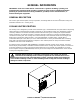
TOP COVER ELECTRICAL CONTROL BOX TOP COVER RETAINING SCREW(2) HYDRO BOOSTR AIR FILTER RETAINING SCREW(4) PLAIN WATER INLET CARBONATED WATER CIRCULATING PUMP CIRCULATING PUMP MOTOR FILTER BRACKET AIR FILTER CO2 INLET CO2 INLET CHECK VALVE SWITCHES ELECTRICAL CONTROL BOX LIQUID DOUBLE CHECK VALVE(2) CIRCULATING MOTOR POWER SWITCH CARBONATOR WATER PUMP(2) CARBONATORS MOTOR POWER SWITCH LEFT-- SIDE PANEL REFRIGERATION POWER SWITCH CARBONATOR TANK(2) SYSTEM ANALYZER TEST PLUG WATER PUMP MOTOR(2) C
REMOTE ROOFTOP CONDENSER COIL AND FAN ASS’Y REFRIGERATION LINES (ITEM 4 AND 5) TOP COVER TOP COVER RETAINING SCREW(2) HYDRO BOOSTR PLAIN WATER INLET CARBONATED WATER CIRCULATING PUMP ELECTRICAL CONTROL BOX CIRCULATING PUMP MOTOR CO2 INLET CHECK VALVE AGITATOR MOTOR CO2 INLET LIQUID DOUBLE CHECK VALVE(2) CARBONATOR WATER PUMP(2) REFRIGERATION LINES CONNECTORS(2) SWITCHES ELECTRICAL CONTROL BOX CIRCULATING MOTOR POWER SWITCH CARBONATORS MOTOR POWER SWITCH REFRIGERATION POWER SWITCH RESET BUTTON WAT
Servicing Carbonator Water Pump Water Strainer Screen. (see applicable Figure 5 or 6 and 8) 1. Disconnect electrical power from Cooling Unit at disconnect switch. 2. Close shutoff valve in plain water inlet supply line. 3. Note pressure setting on carbonator CO2 regulator, then turn regulator adjusting screw to the left (counterclockwise) until regulator gage reads 0-psi. 4. Remove two screws securing Cooling Unit top cover,then remove cover for access to carbonators water pumps.
6. Reassemble check valves as shown in Figure 9. ALWAYS INSTALL NEW BALL SEAT (QUAD RING) P/N 312418000. NOTE: Make sure when assembling check valves together, check valve female end with white tapered gasket inside, is on inlet side of liquid double check valve assembly. 7. Assemble check valves together as shown in Figure 8 . DO NOT OVERTIGHTEN. 8. Make sure white tapered gasket is in place inside female end of liquid double check valve, then install double check valve on elbow in water pump outlet port.
CARBONATED WATER CIRCULATING PUMP MOTOR LUBRICATION (see applicable Figure 5 or 6) Carbonated water circulating pump motor bearings must be oiled periodically. Refer to oiling instructions on motor. DO NOT OVER OIL. ADJUSTMENTS NOTE: To readjust CO2 regulator to a lower setting, loosen adjusting screw lock nut, then turn screw to the left (counterclockwise) until pressure gage reads 5-psi lower than new setting will be.
Index No. 1 2 3 4 5 6 Part No. 317963000 312415000 *312418000 312419000 312196000 317965000 Name Housing Flat Washer, Stainless Steel Ball Seat (quad ring) Ball Spring Retainer * Install new ball seat at each servicing. FIGURE 9. LIQUID CHECK VALVE ASSEMBLY SECONDARY CO2 REGULATORS (see Figure 2) Carbonator Secondary CO2 Regulator. Adjust carbonators secondary CO2 regulator to a nominal 90-psi. Loosen CO2 regulator adjusting screw locknut.
WATER FLOW RATE Refer to Installation Instructions provided with dispensing station for dispensing valve water flow rate adjustment instructions. WATER-TO-SYRUP ‘‘RATIO’’OF dISPENSED PRODUCT Adjust dispensing station dispensing valves for Water-to-Syrup ‘‘Ratio’’of dispensed product as instructed in dispensing station Installation Instructions.
SANITIZING POST-MIX SYRUP SYSTEMS IMPORTANT: Only qualified Service Personnel should perform sanitizing procedure on the post-mix syrup systems. The post-mix syrup systems should be sanitized every 90-days using a non-scented household liquid bleach containing a 5.25 % sodium hypochlorite concentration. Proceed as follows to sanitize the post-mix syrup systems. 1. Disconnect syrup supplies from syrup systems. 2.
C. Continue to activate the dispensing valve in cycles (“ON”for 15-seconds, “OFF”, then “ON”for 15-seconds). Repeat “ON”and “OFF”cycles for 15-cycles. 10. Connect potable water source to the remaining syrup systems and flush detergent solution out of the syrup systems as instructed in step NO TAG preceding. 11. Remove potable water source from the syrup system. STEP 3. SANITIZE SYRUP SYSTEMS 12.
21. Repeat steps NO TAG and NO TAG preceding to purge sanitizing solution out of the remaining syrup systems and dispensing valves. 22. Remove potable water source from the syrup system. STEP 5. PURGE WATER OUT OF SYRUP SYSTEMS (RESTORE OPERATION) 23. Syrup Tank Systems. A. Noting syrup tanks CO2 regulator pressure setting observed in step 4 preceding, readjust CO2 regulator to the observed pressure setting, B. Connect tanks containing syrup into syrup systems. Bag-in-Box Syrup System. C.
6. Open (counterclockwise) CO2 cylinder valve slightly to allow lines to slowly fill with gas, then open valve fully to back-seat valve. (Back-seating valve prevents leakage around valve shaft.) REPLENISHING SYRUP SUPPLY NOTE: The following instructions are applicable only when replenishing same flavor syrup. Refer to SYRUP FLAVOR CHANGE when changing syrup flavor. 1. Disconnect empty soft drink tank from syrup system. 2. Check soft drink tank quick disconnects for sticky or restricted operation.
FIGURE 11.
FIGURE 12.
35 300381000 FIGURE 13.
300381000 36 FIGURE 14.
37 300381000 FIGURE 15.
THIS PAGE LEFT BLANK INTENTIONALLY 300381000 38
TROUBLESHOOTING IMPORTANT: Only qualified personnel should service internal components or electrical wiring. WARNING: If repairs are to be made to a product system, remove quick disconnects from the applicable product tank, then relieve the system pressure before proceeding. If repairs are to be made to the CO2 system, stop dispensing, shut off the CO2 supply, then relieve the system pressure before proceeding.
Trouble Probable Cause Remedy ADJUSTMENT OF DISPENSING VALVE SYRUP FLOW REGULATOR DOES NOT DECREASE TO DESIRED WATER-TO-SYRUP ‘‘RATIO’’. A. Dirty or inoperative piston or cylinder in dispensing valve syrup flow regulator. A. Disassemble and clean dispensing valve syrup flow regulator. DISPENSED PRODUCT CARBONATION TOO LOW. A. Carbonator CO2 regulator out of adjustment for existing water conditions or temperature. A. Adjust carbonator CO2 regulator as instructed. B.
Trouble Probable Cause Remedy ONLY CARBONATED WATER DISPENSED (CONT’D) E. Dispensing valve syrup flow regulator, soft drink tank quick disconnect, or syrup lines restricted. E. Sanitize syrup system as instructed. ONLY SYRUP DISPENSED. A. Plain water inlet supply line shutoff valve closed. A. Open plain water inlet supply line shutoff valve. B. CARBONATOR MOTORS power switch in ‘‘OFF’’ position. B. Place switch in ‘‘ON’’position. C. Water filter clogged. C. Replace water filter. D.
Trouble ERRATIC CYCLING OF CARBONATOR. WATER PUMP MOTOR OPERATES BUT WATER PUMP DOES NOT PUMP WATER WATER PUMP CAPACITY TOO LOW. Probable Cause Remedy E. Binding or damaged balance mechanism. E. Repair or replace balance mechanism. A. Balance mechanism spring obstructed or ‘‘cocked’’. A. Remove obstruction. Make sure spring is perpendicular to spring release and is not twisted. B. Dirty balance mechanism. B. Clean balance mechanism. A. Water pump inlet water strain screen dirty. A.
Trouble COMPRESSOR DOES NOT OPERATE (CONT’D) Probable Cause Remedy I. Hi-pressure cutout tripped (remote Cooling Unit only). I. Reset pressure switch (see REFRIGERATION SYSTEM TEMPERATURE SENSING DEVICE AND HIGH-PRESSURE CUTOUT SWITCH in OPERATORS INSTRUCTIONS SECTION. J. No voltage to control board. J. Check for loose or broken wiring. Check 240/24 VAC power transformer for 24 VAC output. (see NOTE below) K. Inoperative compressor. K. Replace compressor. L.
Trouble COMMPRESSOR OPERATES CONTINUOUSLS BUT DOES NOT FORM SUFFICIENT ICE BANK (CONT’D) Probable Cause Remedy E. Inoperative or disconnected pulse-modulating expansion valve (see applicable REFRIGERATION FLOW DIAGRAM). E. Check that expansion valve is operating by touch (should be able to feel valve pulse).Check for loose or disconnected wire to solenoid coil. If necessary, troubleshoot expansion valve with a gage set to see if it is opening.
WARRANTY IMI Cornelius Inc. warrants that all equipment and parts are free from defects in material and workmanship under normal use and service. For a copy of the warranty applicable to your Cornelius, Remcor or Wilshire product, in your country, please write, fax or telephone the IMI Cornelius office nearest you. Please provide the equipment model number, serial number and the date of purchase. IMI Cornelius Offices AUSTRALIA D P.O.
IMI CORNELIUS INC.