
Installation guide

4
2.6 Installation Procedures
If the Model 230 is supplied with an optional 3-valve or 5 valve
manifold assembly, refer to Section 2.8 and 2.9. Optional 3-Valve
and 5-Valve Manifold Assembly Procedure, for further installation
procedures. If the Model 230 is not supplied with a Setra 3-valve
or 5-valve manifold, the following installation procedure is rec-
ommended.
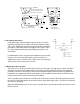
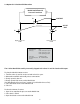
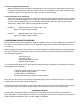
For dierential pressure measurements at high line pressure (350
psig max.), it is recommended that the pressure sensor be in-
stalled with a valve in each line, plus a shunt valve across the high
and low reference pressure ports as shown.
High
Low
Valve C
Valve A
Valve B
High
Low
Dierential
Pressure Sensor
Valve A = High Side
Valve
Valve B = Low Side
Valve
Valve C = Shunt Valve
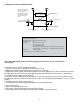
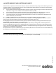
Top View
Transducer Mounting Holes
(screws provided: mounts to
bottom of 230 transducer)
Side View
1.50
38
Conduit Opening
1.63
41
1.63
41
With transducer
mounted to bracket
0.875
22
f
f
Front View
0.43
11
3.00
76
2.50
64
0.52
13
0.88
22
1.30
33
Notched for clamp mounting
0.156
.096
f
f
in.
mm
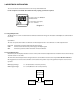
2.7 Bleeding the Pressure Ports
3 bleed screws are on the side of the unit (2 for low pressure port, 1 for high pressure port). Install the
transducer in its intended location and pressurize the ports. Back o the rst bleed screw mounted
on the at side of the sensor body (2 turns max.) until liquid begins to ow out. After only bubble-free
liquid ows out, retighten the bleed screw. Repeat same procedure for the second set of bleed screws
located on the round section of the low pressure tting.
Valve C should be open and Valves A and B closed whenever the system is rst being wetted or pressur-
ized. Valves A and B should then be opened slowly to avoid hammering. Valve C can then be closed and
the system is operating.
When the dierential pressure sensor is to be removed, Valve C must be opened rst, then Valves A and
B can be closed.