
Installation guide

6
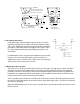
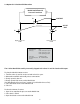
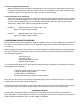
2.9 Optional 5-Valve Assembly Procedure
The 5-Valve Manifold Assembly is normally shipped with valves V1, V2, V4, and V5 closed,
and V3 open.
To Place into service (Unit is mounted vertically):
1. Conrm valves V1, V2, V4, and V5 are closed and V3 is open.
2. Mount the manifold and install process connections to V1 and V2.
3. High Pressure Side: Slowly open V4 to bleed the air out of the high pressure side, close V4 when air stops
bleeding. Open the 2 bleed screws on the high pressure side of the Model 230, see Sec. 2.7, paragraph 1.
4. Install the pressure gauge on V4. Open V4.
5. Low Pressure Side: Slowly open V5 to bleed the air out of the low pressure side, close V5 when air stops
bleeding out. Open the bleed screw on the low pressure side of the Model 230 transducer, see Sec. 2.7, para-
graph 1.
6. Install the pressure gauge on V5. Open V5.
7. System is bled, close V3 to apply dierential pressure to the Model 230.
To take out of service:
1. Open V3 to equalize the pressure.
2. Close the V1 and V2 valves to disconnect pressure supply.
3. Slowly open the low and high pressure bleed ports to depressurize the system.
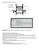
V6
V7
V4
V5
V1 V2
High Process/Commission
1/4”NPT Connection
Low Process/Com-
mission
High Process Connec-
tion
Low Process Connection
1/4”NPT
Note: V6 and V7 bleed
valves are not required
when used with a
Setra Model 230. Use the
bleed screws on Model
230 to bleed the lines
of air.
V3
Model 230
Dierential Pressure Transducer
SHUT OFF VALVES
SHUNT VALVE
5-Valve Manifold Description
(Order as Pressure Code Fitting “5V” See Table below.)
Manifold Block Brass
Valves (5) V1 for connection to ±port
V2 for connection to -port
V3 for equalizing pressure
V4 for connection to external gauge or alternate plumbing conguration
V5 for connection to external gauge or alternate plumbing conguration
Valve Type 90 Degree On/O
Process Connection 1/4 ”-18 NPT Internal Thread