
Installation guide

7
3.0 ELECTRICAL INSTALLATION
To access electrical connections remove cover on top of the Model 230
For CE compliance a shielded cable with both ends properly grounded is required.
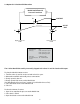
3.1 Voltage Output Units
The Model 230 is a 3-wire circuit with three terminals available for wiring. The -Excitation and -Output are commoned on
the circuit.
Input Power
The 230 can operate from either 9-30 VDC for 0-5 VDC output version or 13-30 VDC for 0-10 VDC output version
Excitation Connected to positive terminal of DC Power Supply
COM Connect as the reference for power supply and output signal
OUT Connect to positive terminal of Control or Pressure Monitor
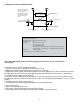
3.2 Current Output Units
Model 230 (current output) transducers are true 2-wire, 4-20 mA current output devices and deliver rated current into any
external load of 0-1000 ohms.
The 4-20 mA current output units are designed to have current ow in one direction only. PLEASE OBSERVE POLARITY.
We suggest that an electrical cable shield be connected to the system’s loop circuit ground to improve electrical noise
rejection.
MIN Supply Voltage: 9 + .02 x (Resistance of receiver plus line)
MAX Supply Voltage: 30 + .004 x (Resistance of receiver plus line)
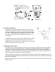
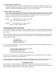
For voltage output, use COM,OUT
and EXC terminals
For current (4-20 mA) output,
use + and - terminals
Diagram 1
Power Supply
Load
(Monitor)
Setra
Transmitter
(4-20 mA)
+
+ +
–
–
–