IMPORTANT SAFETY INSTRUCTIONS Carefully read the following Important information redarding installation safety and maintenance. Keep these instruction for future reference.
Safety Information & Installation Instruction BEFORE YOU BEGIN Read these instructions completely and carefully. ·IMPORTANT — Save these instructions for local inspector’s use. ·IMPORTANT — Observe all governing codes and ordinances ·Note to Installer – Be sure to leave these instructions with the Consumer ·Note to Consumer – Keep these instructions for future reference. ·IMPORTANT — Check the leakage according to the installation instruction.
. If an external electrical source is utilized, a statement that the appliance, when installed, must be electrically grounded in accordance with local codes or, in the absence of local codes, with the National Electrical Code. ANSI/NFPA 70. 4. A statement that: (a) The appliance and its individual shutoff valve must be disconnected from the gas supply piping system during any pressure testing of that system at test pressures in excess of 1/2 psi (3.5kpa).
TABLE OF CONTENTS SAFETY INFORMATION ..................................................................................... 1 FOR YOUR SAFETY …………………................................................................. 1 INSTALLATION PREPARATION........…............................................................ 4 INSTALLATION OPTIONS .................................................................................. 6 DIMENSIONS AND CLEARANCES ................................................................
INSTALLATION PREPARATION PRE-INSTALLATION CHECKLIST 1. When preparing cooktop opening, make sure the inside of the cabinet and the cooktop do not interfere with each other. (See section on preparing the opening.) 2. Slide the cooktop out of the end of the box. Remove packaging materials, grate boxes, regulator and 5 literature package from the cooktop before beginning installation.
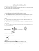
TOOLS YOU WILL NEED FOR INSTALLATION Pencil Phillips-Head Screwdriver Ruler or Straightedge Safety Glasses Pipe Wrench Saber Saw 1/8″ Drill Bit & Electric or Hand Drill ADVANCE PLANNING •Refer to “Installation Preparation” for information on appropriate placement and necessary clearances when planning installation. •Avoid placing cabinetry directly above cooktop when possible. •If cabinetry is used above cooking surface: ——Use cabinets no more than 13″deep.
INSTALLATION OPTIONS Cooktop and Downdraft Vent Combination Installation These cooktops may be installed with a 36” Downdraft Vent. See page 12 for cutout and clearances. ——The countertop must have a deep flat surface to accommodate the combined installation of the cooktop and vent. ——The downdraft vent with blower, motor and ductwork will occupy the base cabinet. ——Consideration must be given to electrical and gas supply locations. See page 8.
3. Make sure the wall coverings, countertop and cabinets around the cooktop can withstand heat (up to 200°F) generated by the cooktop.
POWER SUPPLY LOCATIONS Gas supply: These cooktops are shipped from the factory set for either natural gas or LP gas. Check to be sure you have the correct cooktop for the type of gas being used. ·The pressure regulator must be connected in series with the manifold of the cooktop and must remain in series with the supply line regardless of type of gas being used. ·The natural gas model is designed to operate at 5″ water column pressure.
2. Locate the electrical outlet 12″ below the countertop. Install a manual shut-off valve in the gas line in an easily accessible location outside the cooktop. Be sure you know how and where to shut off the gas supply to the cooktop. Install the electrical outlet 12″below the countertop. Electrical supply: This cooktop features pilotless electric ignition for energy savings and reliability. It operates on a 120 volt, 60 Hz power supply.
Installation Instructions 1. INSTALLING THE COOKTOP A. Remove the screws on the sides of the cooktop burner box. Use those screws to attach the side mounting brackets. B. Insert the cooktop centered into the cutout opening. Make sure the front edge of the countertop is parallel to the cooktop. Check clearances at the front, back and sides. Secure the hold-down bracket to the cabinet sides with screws. 2. INSTALL PRESSURE REGULATOR WARNING: Never reuse old flexible connectors.
OPTION: You can install a 90º elbow (not supplied) onto the gas inlet and route the gas connections to avoid interference when installed over an oven, with a downdraft vent, a warming drawer or other cabinetry features. B. Complete the connection between the regulator and the shut-off valve. C. Before testing for leaks, make sure all burner knobs are in the OFF position. After connecting the cooktop to gas, check system for leaks with a manometer.
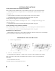
c) Place the burner caps on the burner heads. Make sure that the burner caps are properly seated on the burner heads. Burner cap properly seated Burner cap not properly seated D. Check igniters. Operation of the electric igniters should be tested after the cooktop and supply line have been carefully checked for leaks and the cooktop has been connected to the electrical power. ·Push and turn a burner valve to the LITE position.
·Test each valve separately until all burners have been checked. IMPORTANT: If the igniter electrodes continue to spark after all of the burners are lit, check that each burner component is assembled and properly seated. E. Burner ignition. Cooktop Spark Ignition—When you turn the cooktop knob to LITE, the spark igniter makes a series of electric sparks (ticking sounds) which light the burner. During a power failure, the burners will not light automatically.
OPERATION CHECKLIST 1. Make sure all controls are left in the OFF position. 2. The serial plate for your cooktop is located on the bottom of the burner box. In addition to the model and serial numbers, it tells you the ratings of the burners and the type of fuel and pressure the cooktop was adjusted for when it left the factory. 3. When ordering parts, always include the serial number, model number and a code letter to ensure proper replacement parts.
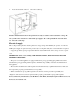
12"min,cutout to wall,both sides. 2-1/2"min,clearance to cutout 22.83“cooktop and vent area cutout 19.3"cutout depth 22.8″X 19.3" depth cut out POWER SUPPLY If local codes permit, the vent and cooktop may operate from the same 120V, 15 amp duplex outlet. Locate the gas and electrical supply as shown on page 8. COOKTOP INSTALLATION OVER A 30″ MONOGRAM SINGLE OVEN These cooktops may be installed over the Monogram single oven.
jurisdiction. Failure to follow instructions could result in serious injury or property damage. The qualified agency performing this work assumes responsibility for the conversion. CAUTION — The following adjustments must be made before turning on the burner. Failure to do so could result in serious injury. Be sure pressure regulator has been converted as described in Step 1. TOOLS YOU WILL NEED FOR CONVERSION Crescent wrench 7mm nutdriver Safety glasses Small flat-head screwdriver (2 to 2.
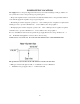
NG position. Take out the retainer. LP position 2 CHANGE BURNER ORIFICES INSTALLATION TIP: First remove all orifices and then start replacing them. This will help to prevent the possibility that some may not be replaced.
A.Remove the burner grates, burner caps and burner heads. B.Using a 7mm nut driver, remove the top burner orifices. There are two orifices per burner. The main orifice is located low in the center of the burner, while the simmer orifice is located higher beside the center of the burner. IMPORTANT: Orifices must be located exactly as shown. Carefully read and observe each orifice label for correct location. C. Install the proper orifices in the exact locations as noted in the illustrations above. D.
·If the flames were too small or fluttered, open the valve more than the original setting. ·If the flames blew away from the burner, close the valve more than the original setting. D.Make the adjustment by slowly turning the screw until flame appearance is correct. E.Testing Flame Stability: Test 1——Turn the knob from “HI” to “LO” quickly. If the upper row of flames goes out at this setting, increase the flame size and test again.
CAUTION — The cooktop, as shipped from the factory, is set for use with its intended gas. If you wish to use your cooktop with the alternate gas, you must first replace the orifices and convert the pressure regulator. WARNING — This conversion must be performed by a qualified installer or gas supplier in accordance with the manufacturer’s instructions and all codes and requirements of the authority having jurisdiction. Failure to follow instructions could result in serious injury or property damage.
NG position Take out the retainer. LP position 2) CHANGE BURNER ORIFICES INSTALLATION TIP: First remove all orifices and then start replacing them. This will help to prevent the possibility that some may not be replaced.
A.Remove the burner grates, burner caps and burner heads. B.Using a 7mm nut driver, remove the top burner orifices. There are two orifices per burner. The main orifice is located low in the center of the burner, while the simmer orifice is located higher beside the center of the burner. IMPORTANT: Orifices must be located exactly as shown. Carefully read and observe each orifice label for correct location. C. Install the proper orifices in the exact locations as noted in the illustrations above. D.
·If the flames were too small or fluttered, open the valve more than the original setting. ·If the flames blew away from the burner, close the valve more than the original setting. D.Make the adjustment by slowly turning the screw until flame appearance is correct. E.Testing Flame Stability: Test 1——Turn the knob from “HI” to “LO” quickly. If the upper row of flames goes out at this setting, increase the flame size and test again.
Solutions to common problems Before calling for service, review this list. It may save you time and expenses. This list includes Common experiences that are nor the result of defective workmanship or materials in your cooktop.