
Installation Manual

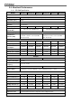
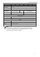

Table of Content
1. IMPORTANT SAFETY INFORMATION 1
1-1. General Safety Precautions 1
1-2. Precautions When Working with Batteries 1
1-3. Installation 2
2. FUNCTIONAL CHARACTERISTICS 3
2-1. General Information 3
2-2. Application 3
2-3. Electrical Performance 4
2-4. Mechanical Drawings 11
3. INTRODUCTION 12
3-1. Power ON / OFF / REMOTE (Main) switch 13
3-2. LED Indicator 13
3-3. DIP Switch (S1~S8) Assignment 14
3-4. DC Input - (please refer to DC wiring connections on P.20) 15
3-5. DC Input + (please refer to DC wiring connections on P.20) 16
3-6. Chassis Ground:Connect the wire # 8 AWG to vehicle chassis 16
3-7. AC Output (Please refer to hard wiring installation on P.21) 16
3-8. By-pass AC input (please refer to hard wiring installation on P.21) 16
3-9. AC input circuit breaker 16
3-10. AC output socket (please refer to 4-2-3. on P.24) 16
3-11. Reset Button (only to be used for Ethernet interface) 16
3-12. CAN1 and CAN2 Port (only to be used in parallel mode) 16
3-13. LCM Port 17
3-14. Green terminal (Remote and Parallel select) 18
3-15. RS-232 Port 18
3-16. Fan Ventilation 19
3-17. Protections Features 19