SP Series User’s Manual SP-700/1000/1500/2000/3000/4000 PURE SINE WAVE INVERTER
Table of Content 1. 2. SAFETY INSTRUCTIONS 1 1-1. General Safety Precautions 1 1-2. Other Safety Notes 2 FUNCTIONAL CHARACTERISTICS INTRODUCTION 3 2-1. System 3 2-2. Block Diagram 3 2-3. Electrical Specification 4 2-3-1. SP-700 Specification 4 2-3-2. SP-1000 Specification 6 2-3-3. SP-1500 Specification 8 2-3-4. SP-2000 Specification 10 2-3-5. SP-3000 Specification 12 2-3-6. SP-4000 Specification 14 2-3-7. Voltage & temperature performance 16 2-4. Mechanical Drawings 3.
4. 5. 6. 3-2-3. General instruction before DC Input 26 3-2-4. Chassis Ground 27 3-3. Maintenance 27 OPERATION 28 4-1. Connection the DC cable 28 4-2. Connecting the input power 29 4-3. Connecting the loads 29 4-4. Switch ON Inverter 29 4-5. Protection Mechanism 30 RS-232 COMMUNICATION AND OPERATION 30 5-1. RS-232 Port 30 5-2. RS-232 Port Operating 31 5-3. Example of RS-232 Port Operating 31 5-3-1. RS-232 command format 31 5-3-2. Command format 31 INFORMATION 36 6-1.
1. Safety Instructions 1-1. General Safety Precautions Warning! Before using the Inverter, read the safety instructions. z Do not expose the inverter to rain, snow, spray or dust. To reduce the risk of fire hazard, do not cover or obstruct the ventilation openings and do not install the inverter in a zero-clearance compartment. z To avoid the risk of fire and electric shock, make sure that the existing wiring is in good electrical condition, and the wire size is not undersized.
1-2. Other Safety Notes z Upon receipt, examine the carton box for damage. If you have found any damage on the carton box please notify the company you purchased this unit from. z Do not operate near water or in excessive humidity. z Do not open or disassemble the inverter, and warranty may be voided. z The DC side connections should be firm and tight. z Grounding: Reliable grounding should be maintained. z Do not drop a metal tool on the battery.
2. Functional Characteristics Introduction 2-1.
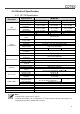
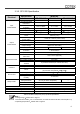
2-3. Electrical Specification 2-3-1. SP-700 Specification Electrical Input Characteristics Output Characteristics Specification Item Voltage Input Over-Voltage M Protection Input Under-Voltage Protection Voltage Range No Load Current Power Saving Mode Continuous Output Power Maximum output Power (1Min) Surge Power (1Sec) Frequency Output Voltage Efficiency max.
Electrical Specification Item Input Characteristics Voltage Input Over-Voltage M Protection Input Under-Voltage Protection Voltage Range No Load Current Power Saving Mode Output Characteristics Continuous Output Power Maximum output Power (1Min) Surge Power (1Sec) Frequency Output Voltage Efficiency max.
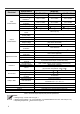
2-3-2. SP-1000 Specification Electrical Input Characteristics Output Characteristics Specification Item Voltage Input Over-Voltage M Protection Input Under-Voltage Protection Voltage Range No Load Current Power Saving Mode Continuous Output Power Maximum output Power (1Min) Surge Power (1Sec) Frequency Output Voltage Efficiency max.
Electrical Specification Item Input Characteristics Voltage Input Over-Voltage M Protection Input Under-Voltage Protection Voltage Range No Load Current Power Saving Mode Output Characteristics Continuous Output Power Maximum output Power (1Min) Surge Power (1Sec) Frequency Output Voltage Efficiency max.
2-3-3. SP-1500 Specification Electrical Input Characteristics Output Characteristics Specification Item Voltage Input Over-Voltage M Protection Input Under-Voltage Protection Voltage Range No Load Current Power Saving Mode Continuous Output Power Maximum output Power (1Min) Surge Power (1Sec) Frequency Output Voltage Efficiency max.
Electrical Specification Item Input Characteristics Voltage Input Over-Voltage M Protection Input Under-Voltage Protection Voltage Range No Load Current Power Saving Mode Output Characteristics Continuous Output Power Maximum output Power (1Min) Surge Power (1Sec) Frequency Output Voltage Efficiency max.
2-3-4. SP-2000 Specification Electrical Input Characteristics Output Characteristics Specification Item Voltage Input Over-Voltage M Protection Input Under-Voltage Protection Voltage Range No Load Current Power Saving Mode Continuous Output Power Maximum output Power (1Min) Surge Power (1Sec) Frequency Output Voltage Efficiency max.
Electrical Input Characteristics Output Characteristics Specification Item Voltage Input Over-Voltage M Protection Input Under-Voltage Protection Voltage Range No Load Current Power Saving Mode Continuous Output Power Maximum output Power (1Min) Surge Power (1Sec) Frequency Output Voltage Efficiency max.
2-3-5. SP-3000 Specification Electrical Input Characteristics Output Characteristics Specification Item Voltage Input Over-Voltage M Protection Input Under-Voltage Protection Voltage Range No Load Current Power Saving Mode Continuous Output Power Maximum output Power (1Min) Surge Power (1Sec) Frequency Output Voltage Efficiency max.
Electrical Input Characteristics Output Characteristics Specification Item Voltage Input Over-Voltage M Protection Input Under-Voltage Protection Voltage Range No Load Current Power Saving Mode Continuous Output Power Maximum output Power (1Min) Surge Power (1Sec) Frequency Output Voltage Efficiency max.
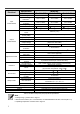
2-3-6. SP-4000 Specification Electrical Specification Item Input Characteristics Voltage Input Over-Voltage M Protection Input Under-Voltage Protection Voltage Range No Load Current Power Saving Mode Continuous Output Power Maximum output Power (1Min) Surge Power (1Sec) Frequency Output Characteristics 48VDC 33 ± 0.5VDC 66 ± 1.0VDC 21 ± 0.5VDC 21~33 VDC 2.0A @24VDC <0.2A @24VDC 42 ± 1.0VDC 42~66 VDC 1.0A @48VDC <0.1A @48VDC Efficiency max.
Electrical Specification Item Input Characteristics Voltage Input Over-Voltage M Protection Input Under-Voltage Protection Voltage Range No Load Current Power Saving Mode Output Characteristics 42 ± 1.0VDC 42~66 VDC 1.0A @48VDC <0.1A @48VDC < 8000 VA Frequency 50 / 60 Hz ± 0.5% (Dip Switch Selectable) Efficiency max.
2-3-7. Voltage & temperature performance Figure 1. SP-700~2000 Figure 2. SP-700~2000 Output power vs. input voltage Output power vs. temperature Figure 3. SP-3000/4000 Figure 4. SP-3000/4000 Output power vs. input voltage Output power vs.
2-4. Mechanical Drawings Figure 5. SP series drawing (Top View) Figure 6. SP series drawing (AC output/Front View) A (mm) B (mm) C (mm) D (mm) E (mm) F (mm) SP-700 Model 330 80 132 200 7.0 83 SP-1000 372 69 196 200 7.0 83 SP-1500 421 92 196 248 7.0 83 SP-2000 443 103 196 248 7.0 83 SP-3000 442 103 196 255 7.0 158 SP-4000 462 113 196 255 7.0 158 Table 13.
3. Installation and Maintenance 3-1. AC Output Side (Front Panel) Introduction Figure 7. SP-700/1000 AC output panel view Figure 8. SP-1500/2000 AC output panel view Figure 9. SP-3000/4000 AC output panel view Model SP-700 SP-1000 SP-1500 Saving power adjustment Function switch Function LED TRC port (RJ-45) Main switch AC output socket SP-2000 SP-3000 SP-4000 AC output terminal Table 14.
3-1-1. Main Switch The 3-stage switch remote mode. is for turning on, turning off and 3-1-2. LED Indicator 3-1-2-1. Input voltage level: to display Input Voltages LED status Red Orange Green Orange Red DC 12V < 11.0V 11.0 ~ 11.5V 11.5 ~ 15.0V 15.0 ~ 15.5V >15.5V DC 24V < 22.0V 22.0 ~ 23.0V 23.0 ~ 30.0V 30.0 ~ 31.0V >31.0V DC 48V < 44.0V 44.0~46.0V 46.0~60.0V 60.0~62.0V >62.0V Table 15. Input Voltage Level LED Indicator 3-1-2-2.
LED status Status Device startup process abnormal Under Temperature Protection (Heat sink temp. under -20 ) Over Temperature Protection (Heat sink temp. over 80 ) Orange Orange Fast Blink Orange Slow Blink Recovery point — >0 < 60 (heat sink temperature) Table 17. Inverter LED Status Indicator 3-1-3. Function Switch Introduction Figure 10. DIP switch ON/OFF position 3-1-3-1.
3-1-3-3. Output Frequency Selection (S3) Frequency 50Hz 60Hz S3 OFF ON Table 20. Function Switch definition: Output Frequency selection 3-1-3-4. Power Saving Selection (S4) Saving function Power Saving OFF Power Saving ON S4 OFF ON Table 21. Function Switch definition: Power Saving selection 3-1-3-5.
Pin Number 4 5 6 7 Signal Description Transfer Relay Driver Signal Internal power for TR40 controller Internal power for TR40 controller The same polarity as the battery negative GND side Reserved -- Bypass 12V 5V 8 Table 24. SP Series TRC Port : RJ-45. Figure 11. Wiring between SP series and TR-40 Note! The detail information please refer to TR-40 user manual 3-1-5. AC output Interface 3-1-5-1.
Socket Type Applicable Model SP-700/1000/1500/2000/3000212/224/248 SP-700/1000/1500/2000-112/124/148 SP-700/1000/1500/2000/3000212/224/248 SP-3000-112/124/148/212/224/248 SP-4000-124/148/224/248 SP-700/1000/1500/2000/3000212/224/248 Table 25. SP Series AC Socket vs. Model 3-1-5-2.
3-2. DC Input Side (Rear Panel) Introduction Figure 12. SP-700/1000 Figure 13. SP-1500/2000 Figure 14. SP-3000/4000 Model ① ② ③ ④ SP-700 SP-1000 SP-1500 Remote port (RJ-11) Remote control green terminal Chassis ground DC input connector SP-2000 SP-3000 SP-4000 Table 27.
3-2-1. Remote Port (RJ-11) The SP Series Inverter can be compatible with CR-8, and CR-16 remote control via RS-232 Communication. Before using the remote control, make sure the main switch on inverter must be at “ REMOTE” position. Pin Number 1 2 3 4 5 6 Signal Description ① Reserved -The same polarity as the battery negative GND side RXD RS-232 RXD TXD RS-232 TXD RMT Remote controller panel (positive) VCC Internal power for remote controller Table 28. SP Series Remote Port : RJ-11 3-2-2.
Note! Fault conditions include Input under / over voltage, output short circuit / over load, over / under temperature. Caution! Please follow the following steps for the installation z Before installing the inverter, make sure the main switch is at “OFF” position. z Before using the remote function, make sure the main switch pressed toward “REMOTE” z Use 20 ~ 24 #AWG wire to connect the remote control terminals Figure 16. Wiring for control 3-2-3.
Model SP-700-112 / 212 SP-700-124 / 224 SP-700-148 / 248 SP-1000-112 / 212 SP-1000-124 / 224 SP-1000-148 / 248 SP-1500-112 / 212 SP-1500-124 / 224 SP-1500-148 / 248 SP-2000-112 / 212 SP-2000-124 / 224 SP-2000-148 / 248 SP-3000-112 / 212 SP-3000-124 / 224 SP-3000-148 / 248 SP-4000-124 / 224 SP-4000-148 / 248 Wire AWG #6 #10 #16 #4 #8 #14 #1 #6 #10 #1/0 #4 #8 #4/0 #1 #6 #1/0 #4 Inline fuse 150A 80 A 50 A 225A 125A 80A 350A 175A 90A 500A 225A 150A 700A 350A 175A 500A 275A Table 30.
4. Operation 4-1. Connection the DC cable Connect DC input terminals to 12V / 24V /48V battery or other DC power source [ + ] is positive, [ - ] is negative. Reverse polarity connection can blow the internal fuse and may damage the inverter permanently. Figure 17. DC cable connection Warning! Make sure that all the DC connections are tight (torque to 9 – 10 ft-lbs, 11.7 – 13 Nm). Loose connections could result in overheating and can be a potential hazard.
Figure 18. Battery cabling 4-2. Connecting the input power Before making the DC input side connections ④, the main switch must be at “OFF”. 4-3. Connecting the loads Calculate the total power consumption of the output load. Make sure that the total power consumption does not exceed the rated power. If the total power consumption over the rated power of the inverter, remove the non-critical: loads until the total power consumption is below the rated power. 4-4.
4-5. Protection Mechanism Over Voltage (DC) Under Voltage Shutdown Restart Under Voltage Alarm Shutdown Restart 12V 16.5V ± 0.3V 14.5V± 0.3V 10.5V ± 0.3V 10.5V ± 0.3V 12.5V± 0.3V 24V 33V ± 0.5V 29V ± 0.5V 21V± 0.5V 21V ± 0.5V 25V ± 0.5V 48V 66 ± 1V 58V ± 1V 42V± 1V 42V ± 1V 50 ± 1V Model Table 31. Protection Mechanism Model Over temperature protection Shutdown Restart 80 60 12V 24V 48V Table 32. Over Temperature Protection Mechanism 5. RS-232 Communication and Operation 5-1.
5-2. RS-232 Port Operating The following steps show the connection among inverter and computer. Step 1 Connect the RS-232 port to the SP series unit on the front panel Step 2 Run the computer communication program Step 3 Set the transmission protocol Byte structure: START-BIP – 8 BIT DATA-STOP BIT Baud rate: 4800 Step 4 Select the COM port and start the operation 5-3. Example of RS-232 Port Operating 5-3-1.
Function Command and description Query the SP series output current Format: IINV? Format: ERR? (SP-700~2000) Bit BIT0 BIT1 BIT2 BIT3 BIT4 BIT5 BIT6 BIT7 BIT8 Query the SP series status BIT9 Description 0: No OLPL Protection 1: OLPL Protection 0:No Sof Fail Protection 1:SofFail Protection 0:No Poff Protection 1:Poff Protection 0:No UVP Protection 1:UVP Protection 0:No OVP Protection 1:OVP Protection 0:No OLPM Protection 1: OLPM Protection 0:No OLPH Protection 1: OLPH Protection 0:No OTP Protection 1: O
Function Command and description BIT8 BIT9 BIT10 BIT11 0:No OTP Protection 1: OTP Protection 0:No UTP Protection 1: UTP Protection 0:No OLPH Protection 1: OLPH Protection 0:No OLPL Protection 1: OLPL Protection * Status definition refer to Table 36.
SP-3000 ~ SP-4000 Status Definition Description Definition ID Sof Fail Protection PLL Poff Protection ID: ID Connection Error Sof Fail: Soft Start Fail PLL: Phase lock loop Poff: Power off OOCP: Output Over Current Protection (Over Load > 200%) OVP: Over Voltage Protection UVP: Under Voltage Protection OTP: Over Temperature Protection UTP: Under Temperature Protection OLPH: Over Load Protection High (116~200%) OLPL: Over Load Protection Low (101~115%) OOCP Protection OVP Protection UVP Protection OTP Pr
5-3-2-4. FUNC 3 : UVP Recovery SETT 12.5 ~ 13.5 25.0 ~ 27.0 50.0 ~ 54.0 Default 12.5V <12.5> 25.0V <25.0> 50.0V <50.0> Model SP series-112 / 212 SP series-124 / 224 SP series-148 / 248 Table 40. UVP recovery 5-3-2-5. FUNC 5 : RS-232 Baud rate SETT 0 1 2 3 Default Model 1200 2400 4800 9600 2 Table 41. RS-232 baud rate 5-3-2-6. FUNC 6 : Retry time SETT 0 1 2 3 Default 3 Table 42.
6. Information 6-1. Warning Warning! Do not open or disassemble the Inverter. Attempting to do so may cause risk of electrical shock or fire. 6-2. Warranty We guarantee this product against defects in materials and workmanship for a period of 24 months from the date of purchase. In case you need to repair or replace any defective power inverters, please contact COTEK local distributor. This warranty will be considered void if the unit has been misused, altered, or accidentally damaged.
No.33, Sec. 2, Renhe Rd., Daxi Dist., Taoyuan City 33548, Taiwan Phone +886-3-3891999 http FAX +886-3-3802333 // www.cotek.com.tw 2016.04.