Woodburning Fireplace Model: SB50HB Installation, Operation and Maintenance Manual for Residential Installation 3" COVER Safety Notice: If this appliance is not properly installed, operated and maintained, a house fire may result. To reduce the risk of fire, follow the installation instructions. Failure to follow instructions may result in property damage, bodily injury or even death. Contact local building officials about restrictions and installation inspection requirements in your area.
SB50HB Series Woodburning Fireplace Congratulations! You have chosen the finest wood burning fireplace available. Your fireplace has been designed for years of heating and viewing enjoyment. Please take time to read this entire manual before installing or operating your fireplace. Table of Contents Listing and Code Approvals.......................................................................................................................... 2 Safety Information.........................................
Safety Information SB50HB Series Woodburning Fireplace Please read this manual before installing and using FIREPLACE. IMPORTANT: Read all instructions and warnings carefully before starting installation. Failure to follow these instructions may result in a possible fire hazard and will void the warranty. Precautions MHSC fireplaces and component parts have been highly tested and will operate safely when installed in accordance with instructions provided in this manual.
SB50HB Series Woodburning Fireplace IMPORTANT INFORMATION 1. Read these instructions entirely before beginning any part of the installation. Save these instructions for any future repairs. 2. Use these instructions as a guide during the installation of the fireplace. 3. Be sure these instructions become the property of and are reviewed by all future users of this fireplace to encourage proper operation and maintenance. 4.
Operation Guidelines SB50HB Series Woodburning Fireplace When an AK4 combustion air assembly and a combustion air duct are attached to the connecting point on the left or right side of the fireplace, combustion air may enter the firebox through a dampered opening behind the left or right side brick. This feature is designed for your benefit to reduce the room air used for combustion and to prevent excessive loss of heat from the room. When the fireplace is in use, this damper should be open.
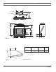
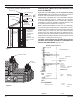
SB50HB Series Woodburning Fireplace FIREPLACE DIMENSIONS 3856O” 11” I.D. Flue 11” 13C\,” O.D.
Clearances SB50HB Series Woodburning Fireplace Figure 3 or Flo eig tH e utl to ht eO Flu Chimney Cap Residential Installation Storm Collar 18’ = Min. Height (No offsets) 24’ = Min. Height (2 30° Elbows) 30’ = Min. Height (4 30° Elbows) 86’ = Max. Height (Chimney Support every 25’) Roof Flashing Chimney Section Maintain 2” Min.
SB50HB Series Woodburning Fireplace Fireplace Location CAUTION: Do not install fireplace over carpeting. This fireplace does not weigh more than large pieces of furniture and can normally be located near a load bearing wall without requiring additional foundations or supports. If however, the fireplace is to be trimmed with a heavy stone or brick facing and hearth extension, be sure the supporting structure is adequate.
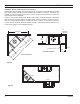
Installation Preparation SB50HB Series Woodburning Fireplace Survey the planned location for the fireplace for overhead plumbing or electrical wires, etc., that might complicate the installation or endanger persons installing or cleaning the chimney. Avoid a location where the chimney cap will be near abrupt changes in the roof shape, nearby wall or embankments, under or near trees or above the roof of a single story wing of a two story building as shown by Figure 8.
Installation Preparation SB50HB Series Woodburning Fireplace Insulating Fireplace Enclosure for Cold Climates Single Story Installation with Attic Space Chimney Cap Flue Outlet Height Storm Collar 3’ Min. or 2’ Above any Point within 10’ Flashing Attic Space See Table 1 for Roof Opening Size 18’ Min.
Floor Protection SB50HB Series Woodburning Fireplace If this fireplace is installed on a combustible floor, the floor area 20 inches in front of, and 12 inches either side of the fireplace opening must be protected by an insulating noncombustible hearth extension. This hearth extension may be either minimum 6-inch thick stone or brick as shown by Figure 10, or a locally constructed hearth equivalent.
SB50HB Series Woodburning Fireplace Floor Protection The ability of insulating material to retard the transfer of heat may be expressed as either Thermal Conductance (C), Thermal Conductivity (K), or Thermal Resistance (R). The mathematical relationship of these values and the formulas for converting one value to another is as follows: C=K divided by the material thickness (Example C = .43 divided by 1/2 (.50) C = .86) K = C multiplies by the material thickness (Example K = .86 multiplied by 1/2 (.
SB50HB Series Woodburning Fireplace MANTEL CLEARANCE MANTEL CLEARANCE Finish the wall with material of your choice. Do not install a combustible mantel shelf less than 18" (457 mm) from the top of the fireplace opening. Do not install a mantel face plate less than 6" (159 mm) from top of fireplace opening. Figure 15. If a combustible material is used below a flat mantel shelf, consult your local building codes for minimum clearance from top of fireplace opening to bottom of mantel shelf.
MANTEL CLEARANCE SB50HB Series Woodburning Fireplace Mantel Clearance with Noncombustible Facing Material Mantel Clearance No Noncombustible Facing Material Combustible Mantel and Trim 12" (305 mm) Max. 156O" Combustible Mantel and Trim Finished Wall Header Noncombustible Material Finished Wall Header 156O" Ledge Bracket 18" (457 mm) min. 6” (152 mm) 12" (305 mm) Max. Ledge Bracket Noncombustible Material 18" (457 mm) min. Surround Face 6" (152 mm) Min.
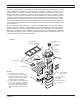
Fireplace Components SB50HB SB50HB Series Woodburning Fireplace AK4 Combustion Air Assembly WSB60 Glass Doors H2074 Hearth Extension Kit 11CF4 11CF3 11CF18 11CF1 Chimney Sections SLTCF11 Chimney Cap 11CS Chimney Support 11CF30-2 Elbow 8-6-12 or 8-12-12 Flashing RLTCF11L Extended Chimney Cap S20UB Upper Baffle S20BR/BT/BW Top Housing FS2A or FS6A Firestop Flat Washer 36” or 72” (13Z\x” Dia. Hole) Fireplace Components Model Description SB50HB 50” front opening fireplace.
SB50HB Series Woodburning Fireplace Fireplace Installation Location Selection Unpack and check the fireplace and chimney for damage. If any items have been damaged, report this to your dealer. Before beginning the installation, be sure you have the proper parts in sufficient quantity. Refer to Page 35 for proper identification of parts. Do not substitute parts. Use only parts listed for use with the Model SB50HB fireplace. Fireplace Installation 1.
Chimney Installation Figure 17 SB50HB Series Woodburning Fireplace 10' 2' Min. 3' Min. 10' 2' Min. 3' Min. AC617 NOTE: Flue outlet should be two feet above all portions of the building within ten feet as shown in Figure 17. The chimney must not extend more than 90 inches above the roof without additional support. AC617 RLTSKC8 2/11/98 1. Lay out, cut and frame openings through all ceilings and the roof at the point where the chimney will pass through.
Chimney Installation SB50HB Series Woodburning Fireplace Centerline of Chimney Actual Center Point Table 1 CHIMNEY HOLE SIZE Plumb Line Size of Chimney 11" CF 2-Wall Angle of Chimney at Ceiling 30˚ Vertical FS2A FS6A 1756O" x 1756O" 17(6 " x 29 6 " (445 x 445 mm) (454 x 753 mm) Plumb Bob Imaginary Center Point Firestop Spacer FP Installation at Attic Level 548b SHR Inlet Air Pipe 5/11/99 djt Flue Pipe Ceiling Joist Figure 18 FP1891 Firestop Spacer Header &P CENTERPOINT Chimney Section
SB50HB Series Woodburning Fireplace Chimney Offset Installation Elbow Installation The following are important points that should be observed when installing elbows on the fireplace: 1. The support straps of all elbows not installed directly on top of the fireplace should be nailed securely to the surrounding structure. This allows the support strap to carry the weight of the chimney above the elbow and prevents this weight from breaking the elbow or chimney sections apart. 2.
SB50HB Series Woodburning Fireplace Chimney Offset Installation Chimney Requirements - Offset Installations OFFSET Chimney Flue Exit RISE Chimney Section FP282 B A 30° Elbow OffsetsIWF282 30° Return Elbow G 1' 1¹⁄₂' 3' 4' G D E 6 FT. C 30° Offset Elbow Rise 30° Return Elbow H Offset 30° Offset Elbow B 11CS Support H Hearth Floor Example 1 Example 2 Notes: G + H cannot exceed 20 feet. *11CF Chimney airspace clearance = 2" minimum.
Chimney OFFSET and Cap Installation SB50HB Series Woodburning Fireplace FS6A 17” Continue chimney to proper height and install round chimney cap or chimney housing C L Figure 25 2256QE” Storm Collar Flashing Roof Firestop Spacer as Required 756M” 7 6QE” 30° Figure 23 Centerline of Chimney FP1894 firestop spacer 8/08 Continue chimney through roof C L and install round chimney cap Fasten Support Straps Securely 2” Minimum Air Space Clearance to Combustibles with use of Firestop NOTE: Two (2) el
SB50HB Series Woodburning Fireplace Chimney Cap Installation Chimney Cap Special Note: The proper height as previously explained is important to assure proper draft and safety. The chimney cap extends the flue outlet four inches above the top of the last section of chimney. This should be kept in mind when determining the proper height for the chimney. The chimney should not be extended more than 90 inches above the supporting roof structure without additional support.
Chimney Cap Chase Installation SB50HB Series Woodburning Fireplace The preinstalled chimney sections should be no more than 13 inches below the top of the chase. The installation should be planned so that either a two-foot or three-foot chimney section will be used for the top section. This is necessary to ensure complete engagement of the inlet air telescope and chimney cap into the top section. 1.
Outside SB50HB Series Woodburning Fireplace Combustion Air Precautions & Recommendations Note: The use of outside air for combustion is optional unless required by building codes. It is only necessary to supply outside combustion air to one side of the fireplace. Use the model AK4 combustion air kit.
Outside Combustion Air Precautions & Recommendations SB50HB Series Woodburning Fireplace Outside Combustion Air Recommendations (continued) 1. Extremely long runs and numerous turns in the duct leading from the fireplace to the combustion air assembly should be avoided. These conditions will increase the resistance to the free flow of air through the duct. Refer to Figures 3, 28 and 29 for methods of installing the outside air for combustion assemblies. 2.
SB50HB Series Woodburning Fireplace Combustion Air Assembly Model AK-4 Combustion Air Assembly 1. Remove the cover plate from the 4-inch outlet opening location on the left or right outside of the fireplace. DO NOT remove the cover if the outside air will not be connected. 2. Place the insulation ring between the AK-4 starting collar and fireplace wall and place the starting collar (4 inch) into the hole on the side of the fireplace. Fasten it in place with the four sheet metal screws provided. 3.
Gas Appliance Installation SB50HB Series Woodburning Fireplace Warning: Improper installation or operation of a gas appliance in this fireplace can allow unburned gas to leak out which will cause a fire or explosion hazard, or the release of poisonous carbon monoxide into the dwelling which can cause serious injury or death to its inhabitants. To reduce these risks to a minimum, the following important notices and instructions should be read and followed carefully. Important Notices: 1.
SB50HB Series Woodburning Fireplace Gas Appliance Installation 7. Pack the insulation removed in step 4 around the pipe to prevent air flowing through the tube either into or out of the firebox. 8. Be sure the gas is turned off at the appliance, then turn the gas on at the shut-off valve and test the gas line connections for leaks with soapy water solution or a liquid leak detector. DO NOT USE A MATCH OR OTHER FLAME SOURCE TO CHECK FOR GAS LEAKS.
Trim and Door Installation SB50HB Series Woodburning Fireplace Installation of Noncombustible Trim Materials to the Front Face of the Fireplace Figure 31 Noncombustible Facing Material Use Only Noncombustible Materials Below Top of Spacers Combustible Framing Members Facing Material to Top of Spacers Fireplace Face Steel Lintel (Optional) CAUTION: Do not cover or restrict vent areas with any trim materials.
SB50HB Series Woodburning Fireplace Fireplace Operation Warning: If a decorative gas appliance is used in the fireplace the fireplace damper must be fixed in an open position. (See additional operation information in section titled “Operation Guidelines”.) Advantages of a Wood Burning Fireplace These are the practical, ecological advantages of wood as a fuel. Also to be considered is the aesthetic appeal. Most of us consider a wood fire with nostalgia.
Fireplace Operation SB50HB Series Woodburning Fireplace You’ll need a minimum of three logs, preferably four, to make a good fire. Add kindling and new logs as needed to rekindle a dying fire. New logs should be added at the rear grate after raking the coals toward the front. Do Not Overfire the Fireplace. Overfire conditions may be created by large amounts of kindling, building scraps, or other improper fuels.
SB50HB Series Woodburning Fireplace Maintenance and Safety Fuel Storage Wood can be dried sufficiently for burning within a few weeks if protected form rain in a low humidity area. It is far better to cut wood and allow it to dry for a year. In all cases, the wood should be stacked so that both ends of the sticks are exposed to the air and protected from rain.
Maintenance and Safety SB50HB Series Woodburning Fireplace Fireplace Maintenance At the end of each heating season or when the fireplace will not be in use for an extended time, the ashes should be removed and the hearth area should be swept as clean as is practical. The slow absorption of moisture into the ashes over a long period of time could cause a condition which would be corrosive to the metal fireplace parts.
SB50HB Series Woodburning Fireplace Maintenance and Safety 17. Do store your fuel supply at a distance equal to or greater than the spacing recommended for combustible materials from the fireplace. 18. Do build fires of moderate intensity in the fireplace for the first three fires to allow materials to adjust and cure before being subjected to the intense heat of a large fire. DON’TS 1. 2. 3. Don’t allow other installations or operation considerations to take priority over safety considerations.
REPLACEMENT PARTS SB50HB Series Woodburning Fireplace 1 6 2 7 3 8 4 5 9 4 Ref. Description Qty. Part No. 1. Rod Damper 1 047647 539027 2. Outside Air Rod/Plate Assy 1 072935 SB6000 parts 3. Panel Fire Screen w/Pull 2 072939 4. Firebrick Side Assy* 2 071476 or 87D0073 5. Grate 1 072954 6. Damper Weight 1 047649 7. Firebrick Back Assy* 1 071474 or 87D0074 8. Handle Damper 1 073716 9.
SB50HB Series Woodburning Fireplace 36 87D0058
SB50HB Series Woodburning Fireplace 87D0058 37
SB50HB Series Woodburning Fireplace 38 87D0058
SB50HB Series Woodburning Fireplace FACTORY-BUILT FIREPLACE AND COMPONENTS (except blowers) What is Covered and For How Long • Five-Year Coverage - For five years from the date this fireplace and components are first purchased for use, MHSC will, at its option, repair or replace any defective part of this fireplace or components, or refund to you a sum not to exceed the factory retail price in effect at the time of purchase.
MHSC 149 Cleveland Drive • Paris, Kentucky 40361 www.mhsc.