COUNTRY FLAME TECHNOLOGIES INSTALLLATION, OPERATION, AND MAINTENANCE MANUAL INGLENOOK FIREPLACE GAS LOG SET MODEL INGLS 24-N OR INGLS 24-P NATURAL GAS OR PROPANE CONVERSIOIN KIT USA & CANADA TEST: Harmonized ANSI Z21.60-2003 CGA 2.26-MO3 & CAN/CGA-21.7.M91 TESTED BY: WARNOCK HERSEY WARNING: If the directions contained in this manual are not followed exactly, a fire or explosion may result causing property damage, personal injury or loss of life.
TABLE OF CONTENTS INTRODUCTION ...........................................................................................................................4 SAFETY INFORMATION .............................................................................................................5 INSTALLATION PREPARATION................................................................................................6 CLEANING ...............................................................................................
TABLE OF CONTENTS NOVA mV SET-UP GUIDE .........................................................................................................31 SAFETY LABEL...................................................................................................................... 32 REPLACEMENT PARTS – INGLS 24N or INGLS 24P .............................................................33 LIMITED 10 YEAR WARRANTY ..............................................................................................
INTRODUCTION THANK YOU and CONGRATULATIONS on the purchase of a new Inglenook gas log kit. The Inglenook fireplace is a solid fuel (wood only) burning appliance; however, many Country Flame customers requested the capability to convert their Inglenook fireplace to a natural gas or a propane gas log set instead of being required to use solid fuel. Inglenook owners are already part of the thousands of members referred to as Country Flame Family.
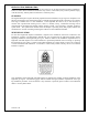
SAFETY INFORMATION - - - The Inglenook gas log kit is designed to be installed only in an Inglenook solid-fuel burning fireplace that has a working flue constructed of noncombustible materials. Maintain a minimum permanent free flue opening of 50.2 square inches provided by the Inglenook fireplace chimney and chimney damper system to vent flue gasses. Maintain this permanent free flue opening by keeping the damper in the fully open position during gas log use. See FIGURE 2.
INSTALLATION PREPARATION IMPORTANT NOTE: Read and comprehend all instructions in this manual before beginning installation. Failure to follow these installation instructions may result in a fire hazard, may result in personal injury, voids the warranty, and may affect a homeowner’s insurance policy. CLEANING The Inglenook fireplace requires advanced preparation before installation of a gas log set is completed.
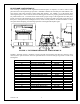
INGLENOOK PARTS REMOVAL Once cleaning or installation of the Inglenook solid fuel fireplace is complete, it is time to remove some parts that will not be required for gas operation. FIGURE 1 identifies each of these parts and TABLE 1 lists each of these parts along with the Country Flame Part Number. Use TABLE 1 as a check sheet when removing these parts. Once removed, the wood burning parts need to be properly packed and stored away for potential future use.
INSTALLATION, GAS LINE Installation of the Inglenook fireplace and the Inglenook gas log kit must conform to National Standards, NFPA 54 (natural gas) or NFPA 58 (propane). The installation of gas line and leak testing must conform to the National Fuel Gas Code ANSI Z223.1 (United States) and CAN/CGA B-149 (Canada) Installation Code and all local codes and gas supplier restrictions. The Inglenook fireplace has been tested and approved for installation using a (7/8" O.D. / 1/2" I.D.
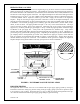
SIT 820 NOVA mV GAS CONTROL VALVE The SIT 820 NOVA mV gas control value is part of the drop in assembly provided with the Inglenook gas log kit. This unit sits in the bottom of the Inglenook fireplace with the SIT 820 extending through the ash grate opening. The SIT 820 NOVA mV gas control valve, when properly located will be visible through the opening in the ash pan housing. Remember, the grate and ash pan were removed in previous steps parts.
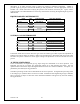
discrepancy or to obtain necessary parts to replace any missing or damaged components. TABLE 2 provides a gas log kit part’s list for both natural gas and propane kits. Use the appropriate version of TABLE 2 as a check sheet while verifying the presence and condition of each kit part. Again, contact Country Flame or an authorized dealer to resolve any issues before converting the Inglenook gas log set to a different fuel.
INGLENOOK GAS LOG KIT SPECIFCATIONS TABLE 3 provides specifications for both Inglenook natural gas and propane gas fuel log kits. The installer and homeowner must understand the differences in these kits both for the type of fuel being used and the impact that altitude has on specific fuel operations. Test procedures for verifying the fuel pressures are provided as part of the SIT 820 control valve operation provided in this manual.
INSTALLATION, BURNERS STEP 1: Once TABLE 1 has been filled in, once all parts have been removed from the Inglenook Fireplace and properly stored, then installation of the gas burner system can begin. FIGURE 5 shows the valve plate assembly that is to be installed in the bottom of the Inglenook in the direction of the arrows. This assembly includes the gas valve and gas line with front and rear gas orifices, the gas valve frame, the base plate, and the pilot valve assembly.
STEP 2: The ember tray and rear burner assembly are now ready for installation. This assembly includes steel tray framing, the rear burner assembly, including the gas tube. Refer to FIGURE 7 to view the installation of these parts. The installation is in the direction of the arrows shown in FIGURE 7. FIGURE 7: BURNER INSTALLATION, STEP 2 FIGURE 8 shows the rear burner tray assembly installed and sitting properly in the bottom of the Inglenook Fireplace.
STEP 3: The front burner assembly is now ready for installation. This assembly includes the front burner tray and adjustable shutter gas tube. This front burner sits into the only opening left from the part installed in STEP 2. It is important to ensure the adjustable shutter tube sit properly over the front gas orifice so that the front burner tray will sit flat into its opening. FIGURE 10 shows the front burner tray sitting in the Inglenook Fireplace.
STEP 4: In STEP 4 the log grate assembly is installed in the Inglenook. This assembly is to be set into the alignment slots provided. FIGURE 12 can be viewed for a look at the proper installation. FIGURE 12: LOG RETAINER, STEP 4 COMPLETE STEP 5: The control panel is installed in STEP 5. The control panel face plate covers the ash pan housing opening. FIGURE 13 shows the control panel faceplate installed. The control panel overlay, control knobs and switches have not been shown for clarity purposes.
INSTALLATION, EMBERS STEP 6: FIGURE 14 shows the embers installed on the front and rear burner. The embers add a “burning ash effect” to the log system when gas is burnt. Embers also help to break up the gas molecules as they pass through the front and rear burner plates and into the burn chamber where these gas molecules combine with oxygen to ensure complete combustion. From time to time, new embers will need to be purchased. FIGURE 14: EMBERS, STEP 6 COMPLETE Version 1.
INSTALLATION, GAS LOGS STEP 7: STEP 7 begins the process of installing the six logs that make up the Inglenook log set. It is imperative that these logs are installed exactly as is shown in FIGURE 15 through FIGURE 21. Failure to install the gas logs correctly will cause the Inglenook gas log system to burn inefficiently. Inefficient gas burns can create a significant amount of soot. WARNING: Do not reconfigure the logs in any different formation other than what is shown in this manual.
FIGURE 17: THIRD LOG INSTALLATION FIGURE 18: FOURTH LOG INSTALLATION Version 1.
FIGURE 19: FIFTH LOG INSTALLATION FIGURE 20: SIXTH LOG INSTALLATION Version 1.
FIGURE 21: COMPLETED GAS LOG INSTALLATION The Inglenook gas log system installation is now complete. The installer can proceed to the first fire and lighting instructions on the next page. The entire system should be carefully monitored for the first several fires until the homeowner is convinced that everything is operating properly.
OPERATING INSTRUCTIONS FOR YOUR SAFETY READ BEFORE LIGHTING WARNING: If you do not follow these instructions exactly, a fire or explosion may result causing property damage, personal injury, or loss of life. A. B. The Inglenook has a pilot light system that must be lit by hand. Follow these instructions exactly, when lighting the pilot. BEFORE LIGHTING the pilot light, it is important to smell all around the Inglenook for potential gas leaks.
MAINTENANCE INSTRUCTIONS The frequency of performing Inglenook fireplace maintenance depends on site-specific conditions and the frequency of use. Country Flame recommends that a certified service technician perform an annual checkup prior to the start of each heating season. Both specific and general maintenance guidelines are presented in this section.
CHECK VENT SYSTEM FREQUENCY: PERFORMED BY: TASK PERFORMED: Once during annual inspection. See General Vent Inspection. Qualified service technician or homeowner. Check complete vent system for corrosion, moisture problems, pinholes or broken seals. Remove chimney cap and inspect vent and cap for debris. Ensure clean and open vent system. GENERAL INSPECTIONS GENERAL VENT INSPECTION Inspect the venting system periodically. Additional areas to inspect are as follows: 1.
GENERAL PERIODIC INSPECTIONS Check the venting system annually and make sure the system is clear of any debris. Check flame patterns periodically. Allow 15 minutes for a flame to reach maximum color and height. GENERAL CLEANING, PAINTED SURFACES Occasionally dry rag dust the Inglenook to keep the painted surface looking new. Paint can be touched up as needed. Clean any area to be painted with fine steel wool. Remove all trim or cover all trim and controls with masking tape.
PROPANE FUEL CONVERSION INSTRUCTIONS The Inglenook gas log kit is shipped from the Country Flame factory set for 65,000 Btu/hr natural gas fuel usage; however, conversion kits may be purcahsed from Country Flame to convert the Inglenook gas log kit to different fuels; propane or natural gas. The Inglneook gas log conversion kit contains different repalcement parts depending on the fuel type specified. Fuel conversion requires adjustment to the control valve, the burners, and the pilot system.
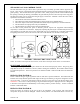
STEP 10 STEP 11 STEP 12 Remove the two burners. Mark each burner as to their location. Refer to FIGURE 4 and TABLE 3 for proper air shutter adjustment for each burner. Adjust each burner’s air shutter to meet fuel conversion requirements. NOTE: Use the shank of an appropriately sized drill bit as an air shutter gauge. Pass the gauge through both sides of the air shutter, adjust and lock the shutter removing the gauge when finished making adjustments.
STEP 14 Open the gas supply and perform gas leak test. One of the best methods used to check for gas leaks is soap bubbles. Soap bubbles are made by mixing liquid detergent with a little water and shaking vigorously to create soap bubbles. Cover the gas pipe joint or valve component with these soap bubbles. If soap bubbles grow in size or the bubbles are blown off the connection, a gas leak exists. Make necessary repairs and retest until no change in soap bubbles is seen at any joint or valve connection.
TROUBLESHOOTING INSTRUCTIONS PROBLEM Pilot will not light. POSSIBLE CAUSE Air in gas lines Defective spill switch. Wrong Inlet Pressure. Defective piezo spark electrode. Defective piezo wire. Pilot will not hold. Safety interlock function engaged. Wrong inlet pressure Pilot adjustment screw not adjusted properly. Thermocouple or thermopile not properly inserted into the pilot housing. Thermocouple or thermopile has film build-up on tip. Electrical resistance too high. Defective thermocouple.
TROUBLESHOOTING INSTRUCTIONS (cont’d) PROBLEM POSSIBLE CAUSE No gas to main burner. Thermostat or wall switch will not cycle main burner Gas pressure to appliance is low. Pilot not lit. Control knob not in ON position. Thermostat not in the ON position. Thermopile output voltage not within design parameters. Defective thermostat or thermostat wiring. Defective wall switch. Excessive wire resistance. Valve wired wrong. Main operator coil defective. Main burner cycles on and off.
TROUBLE-SHOOTING GUIDE The 820 Nova millivolt control valve is available in three different configurations. They are the (1) Millvolt Plus vented, or the (2) Millivolt Plus vent-free, or the (3) Millivolt systems. The Millivolt Plus vented system is for use in direct vent appliances that require fast shut-off in the even of a pilot flame failure. A thermocouple powers the safety magnet and a thermopile powers the main control valve.
NOVA mV SET-UP GUIDE The following information is provided to assist in the set-up of the 820 NOVA mV control valve. A certified professional should install, perform conversions, and verify the proper operation of all Country Flame gas appliances. If there are any questions, please contact a local authorized dealer or Country Flame direct for assistance. 1. 2. 3. 4. 5. 6. 7. 8. 9. 10. 11. 12. 13. Bleed all air from gas lines before starting the system.
SAFETY LABEL FIGURE 29: CONTROL PANEL OVERLAY Version 1.
REPLACEMENT PARTS – INGLS 24N or INGLS 24P When requesting service or replacement parts for your fireplace, please provide model number and serial number. All parts listed in this manual may be ordered from an authorized dealer.
LIMITED 10 YEAR WARRANTY To establish warranty dates a completed warranty card must be received at Country Flame Technologies, 900 George Street, Marshfield, MO 65706, within 60 days of the date of original retail purchase of the Inglenook gas log set. Failure to provide this warranty card within the timeframe specified may require the original retail purchaser to prove the date of installation before any warranty work can be performed.