CPS SC Series Photovoltaic Grid Connection Inverter CPS SC100KT-O/US-480 Installation and Operation Manual Shanghai CHINT Power Systems Co., Ltd.
Table of Contents Chapter 1 IMPORTANT SAFETY INSTRUCTIONS......1 Chapter 2 Overview .....................................................3 2.1 Grid-tie PV system .............................................3 2.2 Inverter circuit structure......................................3 2.3 Appearance ........................................................5 Chapter 3 Installation...................................................6 3.1 Basic requirements.............................................6 3.
4.2.7 Setup of DC Operational parameters ..........27 4.2.8 Setup of operational parameters of MPPT ..27 4.2.9 Power supply from PV to inverter................27 4.2.10 Self-check of power train...........................27 4.2.11 Inverter start-up .........................................30 Chapter 5 Operation ....................................................31 5.1 Start-up and shut-down ......................................31 5.1.1 Start-up .......................................................31 5.
Chapter 8 Quality Assurance ......................................62 8.1 Warranty.............................................................62 8.2 Disclaimer...........................................................62 8.3 Quality clause (Warranty clause)........................
Chapter 1 IMPORTANT SAFETY INSTRUCTIONS (SAVE THESE INSTRUCTIONS) Please read this manual carefully before installation. The warranty will be invalid automatically if the user does not follow this manual during installation and operation resulting in damage to the equipment. ELECTRIC SHOCK HAZARD: All operations and wiring should be performed by qualified technical personnel. Disconnect the inverter from PV assemblies and the Grid before the maintenance and operation of the equipment.
until 15 minutes after all inputs are cut off or the “discharge” command is carried out successfully through LCD button operations. 2. This inverter is specially designed to connect AC power to the public grid. Do not connect the AC output of this equipment directly to private AC power equipments. 3. Please choose the type of inverter based on the way of DC grounding system! Change of PV grounding in the inverter is prohibited without permission.
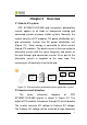
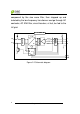
Chapter 2 Overview 2.1 Grid-tie PV system CPS SC100KT-O/US-480 grid connection photovoltaic inverter applies to all kinds of commercial rooftop grid connected system or power station system. Normally, the system consists of PV modules, DC power distribution unit, grid connection inverter and AC power distribution unit (Figure 2-1). Solar energy is converted to direct current through PV modules.
component by the sine wave filter, then stepped up and isolated by the low frequency transformer and go through AC contactor, AC EMI filter, circuit breaker, at last, be fed to the LV grid.
2.
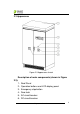
Chapter 3 Installation 3.1 Basic requirements The protection level of CPS SC100KT-O/US-480 photovoltaic inverter is NEMA3R (IP44). Please keep the equipment from direct sunlight exposure if it is installed outdoors. 9 Check and make sure that the ambient temperature of the installation environment is -25 °C ~+60°C; 9 Make sure that the public power grid voltage is 422~528Vac and the grid frequency is 57.0~60.
3.3 Mechanical installation (1) Dimensions Dimensions of CPS SC100KT-O/US-480 grid-tie PV inverter are shown in Figure 3-1.
Conduit area on bottom panel Figure 3-2 Sketch of foundation installation dimensions (2) Requirements of inverter installation: According to the installation dimensions shown in Figure 3-2, secure the inverter on the hard ground or channel steel chassis with M12 foundation bolts through the 8 ¢16 holes at the bottom of the equipment. Front door: A 650mm space should be reserved to ensure that the front door can be opened and closed freely. Back: A 800mm space should be reserved for maintenance.
the machine from the left to the right foot bottom. Then lift the machine slowly to the appropriate location for installation with the crane (shown in Figure 3-4).
Placement of sling rope Figure 3-4 Diagram of lifting with a crane Lifting with a forklift: Adjust the width of the forklift arm within 850mm and insert the fork into the bottom of the machine from the back and lift it to the appropriate location for installation as shown in Figure 3-5.
<850 Figure 3-5 Diagram of lifting with a forklift 3.4 Electrical installation Open the front door of the machine. Proceed as shown in Figure 3-6. 1 、 Turn the handle bar of DC circuit breaker anti-clockwise to horizontal position. 2 、 Turn the handle bar of AC circuit breaker anti-clockwise to horizontal position. 3、Unlock the door with the key. Pull the door knob 45 degree outward to open the front door.
1 3 2 Figure3-6 Diagram of opening front door 4、After opening the front door, remove the transparent Plexiglas cover at the bottom of the machine and connect the external cables to the inverter, as shown in Figure 3-7. The incoming and outgoing cables are routed from the bottom. It is recommended that all the cables are routed along the cable trenches for the convenience of installation and maintenance.
A B Cover I C D E Cover II Figure 3-7 Sketch of external wiring Two ways of routing are available as follows: (1) Routing from square conduit areas at the bottom: Detach the screws from the bottom covers with a cross-shaped screwdriver, remove the two covers and connect cables through the square conduit areas. (2) Routing from round holes on the bottom cover: (a) Remove the cover screws, put the screws aside, and then take off the two covers.
for the AC cables and grounding cable. A,B:Conduit for DC cables C: Conduit for communication cables D: Conduit for AC cables E: Conduit for the grounding cable (c) Punch holes on the bottom cover for the conduits; (d) Check the seal of the cover; (e) Restore the cover to the equipment,attach the screws; (f) Insert the conduits into the openings; (g) Attach the conduits with the appropriate hubs. 3.4.
Table 3-2 4 strings 3 strings 2 strings Positive 2AWG(35mm²) 1/0AWG (50 mm²) 3/0AWG (95 mm²) Negative 2AWG(35mm²) 1/0AWG (50 mm²) 3/0AWG (95 mm²) Bolts M10 bolts (torque value:10N-M or 88.5Lb-In.) (2) Confirm that the input PV modules are of the same specifications and types before connection of DC input; (3) Connect the DC cables to the inverter’s copper bar terminals of DC side according to the Table 3-3, as shown in Figure 3-8 and 3-9.
GFDI board Return Hot PV– of DC cables PV+ of DC cables Figure 3-8 DC connection of CPS SC100KT-O/US-480 GFDI board Return Hot PV+ of DC cables PV- of DC cables Figure 3-9 DC connection of CPS SC100KT-OPG/US-480 16 Chapter 3 Installation
The schematic diagram of wire connection is shown in Figure 3-10. Outside the inverter Hot Inside the inverter + = PV+ - PVReturn ~ GFDI Negative ground Hot + = PV- - PV+ Return ~ GFDI Positive ground Figure 3-10 Schematic diagram of DC side The type of fuse is shown in Table 3-4. If a large stream of electric current passes through, the fuse will be disconnected and the GFDI circuit will detect the fault. Solution of the problem may refer to “5.3 Troubleshooting”.
3.4.2 AC and ground connection Connect the AC output of PV inverter to the AC cabinet or the power grid through AC output and grounding cables: (1) Use the recommended copper cored cables with an insulation rating of 90℃, as shown in Table 3-5: Table 3-5 Connection terminals Wire L1 L2 L3 Gnd 2/0AWG(70mm2) 2/0AWG(70mm2) 2/0AWG(70mm2) 2AWG(35mm2) diameter Bolts M10 bolts (torque value:10N-M or 88.5Lb-In.
of the ground bar. Terminal G Terminal G Figure 3-12 Ground connection (4) Make sure that all cables are tightened on L1, L2, L3 and G terminals properly. 3.4.3 Communication connection (1) RS485 communication connection (Standard configuration): The signal pinboard on the inverter has 3 RJ45 communication connectors, which are RS485-1, RS485-2 and Ethernet terminals, as shown in Figure 3-13. Customers can connect the communication cables by themselves.
RS485-1 RS485-2 Ethernet Figure 3-13 Signal cable terminals for communication (2) The communication of one single local inverter can be connected from the RS485-1 or RS485-2 port on the inverter to 485 bus bar directly. (3) For remote monitoring of more inverters, connect the RS485-1 port of one inverter to the RS485-2 port of another inverter and then connect to the data logger (Interlink) through the 485 bus bar to send data to the background monitoring system.
(4) Requirement of communication cables: Shielded cables should be used for communication cables with maximum length of 1000 meters. The wiring requirements of RS485-1/2 connector are shown in Table 3-6 and the way of connection is shown in Figure 3-14. Cables 1~8 are shown from left to right. Table 3-6 No. Color Function 1 White orange 485+ 2 Orange N.C. 3 White green 485- 4 Blue N.C. 5 White blue N.C. 6 Green N.C. 7 White brown GND 8 Brown N.C.
transmission running on TCP/IP protocol, as shown in Figure 3-13. Shielded twisted pair (STP) is recommended for the communication cables. Both terminals of a communication line should conform to the 568B standard. 3.4.4 Connection of dry contact The connection of dry contact is shown in Figure 3-15. The two terminals are potential-free contacts for fault alarming of the inverter. The wiring requirement is shown in Table 3-7.
Baffle Figure 3-16 Diagram of baffle installation 23 Chapter 3 Installation
Chapter 4 Initial On-grid Testing To ensure operational safety, initial on-grid testing is required as per the instructions in this chapter before connecting PV array and grid power after the installation of CPS SC100KT-O/US-480. 4.
Make sure that the DC circuit breaker and AC circuit breaker are turned off. Open the front door of the inverter and ensure the electrical components and connections are normal. (2) Check and make sure that all the cables are well connected and there is no wire looseness, short circuit or insulation loss, etc. (3) Correct any problems identified. 4.2.2 AC connection checking (1) Check whether the power grid A, B, C, PE cables are tightened on L1, L2, L3 and G terminals correspondingly and properly.
check whether the cable connection from DC source to the inverter is correct. (3) Confirm whether the polarity of DC connection is correct. (4) Correct any problems identified. 4.2.4 Power supply from grid to inverter (1) Close the front door of the inverter. (2) Turn on the AC circuit breaker. The auxiliary power supply of the inverter is energized and the control circuit is started up. (3) Check carefully whether there is abnormality, including noise or smell.
4.2.6 Setup of AC Operational parameters Enter “1 SysPara” menu according to “6.3.7 System protection parameter setup”. (1) Check the AC voltage, frequency protection value and time of protection actions. (2) Change the parameters if necessary. 4.2.7 Setup of DC Operational parameters (1) Check the PV start voltage and time of the inverter. (2) Change the parameters if necessary. 4.2.
and locked up. Then turn on the AC and DC circuit breaker. (2) Wait for the inverter to stand by, the status of which will be indicated on the LCD. (3) Select “2 PowerTrain” on the LCD and press “ENT” according to “6.3.6 System setup”. Then self-check interface will be indicated on the LCD. (Figure 4-1) After pressing “ENT”, the system begins self-checking of power train. (Figure 4-2) PowerTrain? Figure 4-1 Self check confirmation interface PowerTrain..
Low PV Volt Figure 4-3 Low Volt (5) If “PowerTrainFualt” is indicated on the LCD, as shown in Figure 4-4, check whether the DC circuit breaker is turned on. Then check whether the inverter is in “ON State” according to “6.3.6 System setup”. If the fault still occurs when the DC circuit breaker is turned on and the inverter is “ON State”, please contact our after-sale service personnel. PowerTrainFault Figure 4-4 Self check fails (6) Restart the self-check of power train when the fault is fixed.
PowerTrain OK Figure 4-5 Self check OK (7) Turn off the AC and DC circuit breakers if anything abnormal happens. 4.2.11 Inverter start-up (1) If the PV voltage exceeds the starting voltage (adjusted automatically with the grid voltage and 330V is the default minimum voltage.) and the grid voltage meets the requirement of grid connection, the contactor inside the inverter will be picked up to energize the inverter to start up after several minutes under stand-by mode.
Chapter 5 Operation Warning: To ensure operational safety, conduct the initial on-grid testing before operating on the CPS SC100KT-O/US-480. 5.1 Start-up and shut-down 5.1.1 Start-up Turn on the DC and AC circuit breakers. Manual start-up: Manual start-up is required after initial installation or manual (fault) shut-down. Move the cursor from the main operation interface to“4 Setting” according to “6.3.6 System setup”. Press ENTER and go to submenu “1 ON/OFF”.
necessary. It can be shut down manually if repair or maintenance is required. (1) Move the cursor from the main operation interface to “4 Setting” according to “6.3.6 System setup”. Press ENTER and go to submenu “1 ON/OFF”. The inverter will be shut down and enter “OFF State” after moving the cursor to “OFF” and press ENTER. (2) Press the “emergency stop button” on the panel to shut down the inverter in case of emergencies. The inverter is still in “ON State” after it is shut down by emergency button.
AC circuit breaker is turned on. (2) Referring to “6.3.6 System setup”, move the cursor from the main operation interface to“4 Setting”, press ENTER and go to submenu “6 OtherCmd”. Then move the cursor to “1 De-energy” and press ENTER, as shown in Figure 5-1. After pressing ENTER to confirm, the DC bus capacitor begins to discharge, as shown in Figure 5-2.
Figure 5-3 De-energy OK interface (4) If “De-energy” fails, as shown on the LCD in Figure 5-4. It takes at least 15 minutes for the inverter to discharge automatically after turning off the AC circuit breaker. The inverter should not be maintained until the voltmeter shows that there is no electric charge left in the DC bus capacitor. Figure 5-4 De-energy error interface (5) If the DC circuit breaker is not turned off, LCD will remind of “TurnOff DC Break”, as shown in Figure 5-5.
Figure 5-5 Turnoff DC circuit breaker 5.2 Operation mode There are 4 operation modes. The following are corresponding indications for each mode. (1) System check mode is shown in Figure 5-6: System is in self check status when inverter is energized. The program will complete initialization in this status.
Figure 5-7 Inverter system in standby (3) Normal operation mode, as shown in Figure 5-8: The inverter will turn from standby into normal operation mode when the output voltages of PV panel and power grid meet the startup conditions as long as the inverter is “ON State”. In this mode, the inverter converts the power generated by PV modules to AC continuously and feeds to the power grid.
into fault mode when the PV power generation system fails. Check the fault information on the LCD, which may be referred to “6.3.4 Present fault” and “6.3.5 History”. Specific cause can also be found in “5.3 Troubleshooting” and corresponding instructions are available to eliminate the faults. Figure 5-9 Fault indication interface 5.3 Troubleshooting There are mainly three fault alert statuses: Warn, Protect and Fault.
2. Run the “2 Restart” command to reboot the system according to “6.3.7 System protection parameter setup”. The causes of fault can be identified based on the faults listed in Table 5-1. Please contact our after-sales service if the fault persists.
Warn/Protect/ Recommended Definition Possible causes Fault 5、 Warn0050 6、 Warn0020~0150 Protect 1、 TempOver solutions 2、PV over-current; 2、Check DC breaker; 3、DC breaker is 3、Check PV cable damaged; connection; 4、Circuit inside DC 4、Check whether the breaker is loose sunlight is too strong or the configuration of PV panel is reasonable; 5、Contact after-sales service personnel 1、Observe for 5 minutes and see 1、Temperature whether the alarm will inside inverter be eliminated exceeds normal automatical
Warn/Protect/ Recommended Definition Possible causes Fault 2、 GridV.OutLim solutions Grid voltage exceeds the specified range, or grid is not detected 1、Grid voltage is abnormal; 2、Power grid outage 3、Cable connection between the inverter and the grid is disconnected 1、Grid frequency has abnormalities; 2、Power outage of Grid voltage the grid; frequency is 3、Cable 3、GridF.OutLim abnormal, or grid connection is not detected between the inverter and the grid is disconnected 4、PV.
Warn/Protect/ Recommended Definition Possible causes Fault 5、PV.Reverse 6、AC.
Warn/Protect/ Recommended Definition Possible causes Fault solutions 1、 Observe for 10 minutes and see whether the alarm will 9、 Internal protection Internal protection be eliminated Protect0010~0620 of inverter of inverter automatically; 2、Contact after-sales service personnel 1、The inverter can be forced restarted once if it is required by operation and if it is confirmed that there is Fault inside Serious fault occurs Fault Fault0010~0160 no other problem inverter inside inverter according to “6.3.
replaced. 5.4.1 Replacement of filter net on the top Steps of replacement are shown in Figure 5-10: (1) Screw off the M3 bolts in the middle of the filter net with 2# cross-shaped screwdriver and take off the fixed plate. (2) Push aside the two clips on both sides and disassemble the filter net. (3) Clean the filter net and put it back or replace with a new one.
Filter net Figure 5-10 Diagram of filter net disassembly (top) 5.4.2 Replacement of internal filter net The instructions of “5.1.2 Shutdown” should be followed before opening the inverter for maintenance. Electric shock hazard: All operations and wiring should be performed by qualified technical personnel. Disconnect the inverter from PV assemblies and the power Grid before the maintenance and operation of the equipment.
Backboard 后门 Figure 5-11 Disassembling of backboard (3) Screw off the fixed bracket of filter net and take out the filter net at the bottom of the transformer, as shown in Figure 5-12.
fixed bracket of Filter net filter net Figure 5-12 Diagram of filter net disassembly (internal) (4) Clean the filter net, put it back or replace with a new one and then reinstall the backboard.
Chapter 6 Human Machine Interface 6.1 Description of LCD display CPS SC100KT display mainly consists of LCD screen, LED indicator lights, buzzer and 6 keys. Meanings of indicator lights are shown in Table 6-1 and functions of the keys are shown in Table 6-2.
Table 6-2 Definitions of the keys Key Description Definition of function Escape key Enter key Back/end/mute Confirm entering the menu/confirm set point PAGEUP( ) Up Page up in selection menu PAGEDOWN ( ) Down Page down in selection menu ADD( ) Left +1 when setting parameters DEC( ) Right -1 when setting parameters ESC( ) ENTER( ) 6.2 Operation state Table 6-1 indicates the definitions of LED, i.e. indicates the information of the inverter’s operation state.
“FAULT” will not light up if both the inverter and grid are normal. The buzzer will give alarms if a fault (involving power grid abnormality) occurs. 6.3 Interface and menu functions Users can perform the corresponding operations with the 6 function keys according to the indications of the LCD display. 6.3.1 Interface types (1) The LCD interface starts with the company logo once the system is energized as shown in Figure 6-1.
Figure 6-2 Inverter system check ongoing Figure 6-3 Inverter system in standby mode Figure 6-4 Default display interface for normal operation Figure 6-5 Fault indication interface 50 Chapter 6 Human Machine Interface
LCD screen will display different mode interfaces based on the operation modes of the inverter. There are four operation modes: startup system check mode (as shown in Figure 6-2), stand-by mode (as shown in Figure 6-3), normal operation mode (as shown in Figure 6-4) and fault mode (as shown in Figure 6-5). The default indication interface mainly indicates PV voltage, PV current, grid voltage, generation power, instant generated power and time information under normal operation.
The main operation interface of LCD screen has 4 level-1 menus, i.e. “1 OP. Info”, “2 Alarm”, “3 History” and “4 Setting”. The users may select options with PAGEUP and PAGEDOWN, and then press ENTER to confirm selection. The users can return to the default indication interface by pressing the ESC key. 6.3.3 Operation information When the cursor moves to “1 OP. Info” in the main interface, press ENTER to select the operation information as shown in Figure 5-7.
6.3.4 Present fault As described before, when faults occur during the normal operation of the inverter, corresponding fault message will be indicated in “2 Alarm” menu besides the sound and light alarms. Move the cursor to “2 Alarm” and press ENTER to check out the specific fault information (50 pieces of fault information can be indicated at the same time), as shown in Figure 6-8. 2 Alarm If no exiting Else exiting No Alarm SPICommErr IntProtectA … Figure 6-8 Present fault information 6.3.
interface. The users can select the “2 OP. Recd” menu and input the retraceable days (For example, the input number is 21. If the current date is December 15th, the LCD will indicate the operation information of 21 days before that date which is November 24th). (3) Software version, hardware version and serial number of the product are listed in “3 Version” menu. (4) Accumulative generated electric power since the first day the inverter began working is available to be found in “4 TotalTag” menu.
6.3.6 System setup Move the cursor to “4 Setting” in the main interface. Press ENTER to set the current system parameters, as shown in Figure 6-10. There are 6 submenus in “4 Setting” : “1 ON/OFF”, “2 Language”, “3 Buzzer”, “4 SysTime”, “5 Commun” and “6 OtherCmd”. (1) The inverter can be started and shut down with “1 ON/OFF” menu.
specific date and time by pressing Left and Right. (5) Set the 485 communication parameters (including the address and baud rate of inverter) with “5 Commun.” menu. (6) In “6 OtherCmd” menu, run “1 De-energy” to discharge the electric charges of DC capacitor quickly; run “2 PowerTrain” to check the status of main system circuit for the initial on-grid testing.
time in the main interface and entering the password (PAGEUP->PAGEDOWN->RIGHT->LEFT), the system parameter setup menu is entered. This menu includes 4 submenus: “1 SysPara”, “2 Restart”, “3 Recover” and “4 ClrErrRecd”. (1) Set up the system protection parameters in “1 SysPara” menu. The types of protection parameters are shown in Table 6-3. (2) “2 Restart” menu. If an internal fault shutdown happens, a severe fault has occurred inside the inverter.
Figure 6-11 System parameter setup Table 6-3 Protection Parameters Table No. 1 2 3 Setup range (lower Description of LCD indication parameter limit) Grid voltage upper GridV.Max(V) (527, 527, 575) GridVmaxTripT(S) (0.16, 1.00, 1.00) GridV.Min(V) (240, 422, 422) limit (V) Trip time under Max.
No. 4 5 6 7 8 Setup range (lower Description of LCD indication parameter Trip time under Max. voltage (S) limit, default & upper limit) GridVminTripT(S) (0.16, 2.00, 2.00) GridF.Min(Hz) (57.00, 59.30, 59.80) GridFTripT(S) (0.16, 0.16, 300.00) Grid frequency lower limit (Hz) Frequency trip time (S) Active power PowerDerating derating (%) (%) Reactive Compensation (10%, 100%, 100%) ReactiveComp (-0.900, 1.000, 0.
Chapter 7 Technical Data CPS SC100KT-O/US-480, CPS SC100KT-OPG/US-480 DC Input Nominal DC Voltage 400Vdc Max. DC Voltage* 600Vdc MPPT Voltage Range 300~550Vdc Operating Voltage Range 300~600Vdc Max. DC Power 110KW Max. Input Current 350A Max. DC Short Circuit Current 410A Number of MPP Tracker 1 AC Output Output Power 100KW Nominal Grid Voltage 480Vac 3phase Allowable Grid Voltage** 422~528Vac Nominal Grid Frequency** 60Hz Current THD <3% Power Factor ~1 System Max.
Power consumption overnight <50W Certification General Standard UL1741 Rev 2010, IEEE1547, Radiated Emission FCC PART15, Class A Display and communication Standard Communication RS485 Optional Communication Ethernet Fault Alarm Dry contact (MAX 240VAC, 2A) Display LCD Display Mechanical parameters WxDxH(mm) 1200×1850×880 Weight (kg) 900kg *Note 1: Exceeding the rated voltage shown in “Maximum DC voltage” may cause permanent damage to the equipment.
Chapter 8 Quality Assurance 8.1 Warranty The warranty policy of this product is specified in the contract; otherwise the warranty period is 24 months since the date of installation. 8.
repair work. Please do not hesitate to contact us if you have any questions about CPS SC100KT-O/US-480 PV grid connection inverter. We will be glad to provide the best service for you at any time.
Shanghai CHINT Power Supply System Co., Ltd. Headquarters: Building 4, No. 855, Wenhe Road, Songjiang District, Shanghai, China Extension: +86-021-37791222 Fax: +86-021-37791222-6001 Website: www.chintpower.com Service hotline: 021-37791222-6300 Email: service.cps@chint.com CPS SC100KT-O/US-480 Installation and Operation Manual (PN: 9.0020.0041A0) is printed for the first time. This manual is subject to change without prior notification. Copyright is reserved.