CPS SC Series Grid-tied PV Inverter CPS SC20KTL-DO/US-480 Installation and Operation Manual CHINT POWER SYSTEMS AMERICA CO., LTD.
Table of Contents Before You Start… ..........................................................1 Chapter 1 IMPORTANT SAFETY INSTRUCTIONS......2 Chapter 2 Overview .....................................................4 2.1 Inverter for grid-tied PV systems ........................4 2.2 Product type description .....................................4 2.3 Product features .................................................5 2.4 Circuit structure design .......................................6 2.
4.4 Fault shutdown ................................................... 38 Chapter 5 Human Machine Interface .......................... 38 5.1 Description of LCD panel ................................... 38 5.2 Operation state ................................................... 39 5.3 Interface and menu functions ............................. 40 5.3.1 Interface types ........................................... 40 5.3.2 Main operation interface ............................ 42 5.3.3 Operation information ...
Before You Start… This manual contains important information regarding installation and safe operation of this unit. Be sure to read this manual carefully before using. Thanks for choosing this Grid-tied PV Inverter (referred to in this manual as “PV Inverter”, or simply “Inverter”). This Grid PV Inverter is a highly reliable product due to its innovative design and perfect quality control. Such an Inverter is used in high demand, grid-tied PV systems.
Chapter 1 IMPORTANT SAFETY INSTRUCTIONS (SAVE THESE INSTRUCTIONS) Please read this manual carefully before installation. CPS reserves the right not to guarantee the quality for equipment damage if the user fails to install the equipment as per the instructions in this manual. ELECTRIC SHOCK HAZARD: All operations and wiring should be performed by qualified technical personnel. Disconnect the inverter from PV modules and the Power Grid before the maintenance and operation of the equipment.
avoid reducing conversion efficiency due to excessively high internal temperature of the machine. CAUTION: Steel conduits as the cable protector need to be prepared by the customers before installation. HIGH TEMPERATURE: Although designed to meet international safety standards, the PV-Inverter can become hot during operation. Do not touch the heat sink or peripheral surfaces during or shortly after operation. HIGH TEMPERATURE: The inverter and peripherals can be hot after operation.
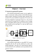
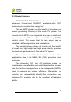
Chapter 2 Overview 2.1 Inverter for grid-tied PV systems CPS SC20KTL-DO/US-480 inverter can be applied to various commercial rooftop systems and distributed power station systems. Normally, the system mainly consists of PV modules, DC power distribution equipments, PV inverter and AC power distribution equipments (Figure 2-1). The inverter converts the DC energy from PV modules to the AC energy that is compatible with the public grid.
2.3 Product features CPS SC20KTL-DO/US-480 inverter incorporates the advanced 3-level and MOSFET paralleled with IGBT technology to minimize the energy loss. The two-MPPT design has the benefit of increasing the power generating efficiency of the whole PV system. The inverter has 2 MPPTs, so a separate array can be controlled by an independent Maximum Power Point Tracking (MPPT) control circuit. This means that the two arrays can be installed in different positions and orientations.
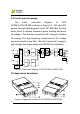
2.4 Circuit structure design The basic schematic diagram of CPS SC20KTL-DO/US-480 is shown in Figure 2-2. The input DC passes through lightning-proof circuit, DC EMI filter, and the boost circuit to achieve maximum power tracking and boost up voltages. The inverter converts the DC energy to 3-phase AC energy. The high frequency components of AC voltage are removed with a line filter. Then the 3-phase AC energy is sent through two-stage relays and EMI filter for outputting.
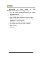
Description of main items of CPS SC20KTL-DO/US-480 (shown in Figure 2-3): 1、LCD key buttons: operate the functions and change settings of inverter 2、LCD display: indicates data 3、LED indicator lights: indicate the status of inverter 4、DC input (4), AC output & ground terminals (1) and signal port (1) from left to right 5、DC switch: control the DC power on and off 6、AC switch: control the AC power on and off 7、Main housing 8、Wiring box 7 Chapter 2 Overview
Chapter 3 Installation Below is the installation instruction of the inverter. Please read carefully and install the product step-by-step. 1. CPS SC20KTL-DO/US-480 Check and make sure that the following items are included in the package before installation, as shown in Table 3-1.
bolts & nuts pairs for backup use) M5 nut 2 Ring terminal 1 for grounding wire (1 nut for backup use) for grounding wire 16 for input wires, 3 for Cord end terminals 20 output wires, 1 for neutral wire (optional) RJ45 connecters 4 Red wire 1 Black wire 1 for communication cables for inverter with 1 MPPT working alone for inverter with 1 MPPT working alone 3.
9 Sufficient convection space; 9 Away from flammable and explosive substances. 3.2 Mechanical installation (1) Dimensions The dimensions of CPS SC20KTL-DO/US-480 inverter are shown in Figure 3-1. Figure 3-1 Dimensions of CPS SC20KTL-DO/US-480 (2) Check whether the place to mount the inverter is appropriate: (a) It’s better to mount the inverter in a vertical position. (b) If the inverter cannot be mounted vertically, it is allowed to be tilted backward by Max. 15°.
(c) Do NOT mount the inverter forwards. (d) Do NOT mount the inverter in a horizontal position. (e) Do NOT mount the inverter upside down.
objects should meet the following conditions: two sides from the walls ≥11.81 inches; top distance ≥11.81 inches; bottom distance ≥23.62 inches; the minimum spacing between two inverters in parallel ≥11.81 inches.
Figure 3-4 Bracket mounting dimensions (b) Drill holes at the marked positions with a diameter of 0.
Figure 3-5 Positions of bolt holes on the bracket (d) Screw off the bolts and remove the two panels on both sides of the inverter as shown in Figure 3-6; Figure 3-6 Removal of panels before mounting inverter (e) Two people grab at the position on each side, lift up the inverter and then hang it on the bracket (Figure 3-7a~e).
Hand Grab Figure 3-7a Mounting inverter on the bracket Figure 3-7b Mounting inverter on the bracket 15 Chapter 3 Installation
Figure 3-7c Mounting inverter on the bracket Figure 3-7d Mounting inverter on the bracket 16 Chapter 3 Installation
Figure 3-7e Mounting inverter on the bracket (f) Put the two removed panels back and secure them with 4 M4*12 bolts on each side, as shown in Figure 3-8.
3.3 Electrical installation CAUTION: Steel conduits as the cable protector need to be prepared by the customers before installation.
under any conditions; (b) The inverter has 2 MPPTs. Ensure that the Max. DC input current of each MPPT does NOT exceed 35A. (c) Confirm that the PV modules for each MPPT of the inverter are of the same types and specifications before connection. The number, orientation, and tilt of PV modules may differ for different application.
7 16~10 strings AWG 6 16~10 strings AWG 1 PV1+ 2 IN1+ 3 4 1 PV1- 4 2 IN1- 14~10 3 4 Inverter 1 strings PV2+ 2 IN2+ 3 AWG 4 1 PV2- 2 IN2- 3 4 Note 1 : The DC fuse protectors of different fusing capacity should be chosen according to the short circuit current of PV modules. The 600VDC Littelfuse KLKD fuse series are recommended. The detailed information is available for customers to find and download from http://www.littelfuse.com/.
The recommended fuse types are listed in the following table: Table 3-4 Recommended fuse types DC input 2 strings/MPPT 3 strings/MPPT 4 strings/MPPT Fuse KLKD 30 KLKD 15 KLKD 15 Note 2: Concerning the current share of fuse for each DC input string, 1 or 2 DC input strings are NOT recommended.
(b) Insert the cables through steel conduits and strip the skin 0.4 inch off the cables as shown in Figure 3-10: Figure 3-10 Diagram for wire stripping of DC input (c) Crimp the terminal as shown in Figure 3-11: Figure 3-11 Diagram for terminal crimping of DC input (d) The order of wire connection from left to right is PV1-, PV1+, PV2-, PV2+.
Figure 3-12 Diagram for wire connection of DC input (e) For the inverter with 1 MPPT working alone, connect J1 (IN1+) with J3 (IN2+) wire socket (in the Wiring box) through the red wire in the accessory kit; Connect J2 (IN1-) with J4 (IN2-) wire socket through the black wire in the accessory kit, as shown in Figure 3-13: 23 Chapter 3 Installation
Figure 3-13 Diagram of wire connection in the Wiring box for inverter with 1 MPPT working alone 3.3.2 AC and ground connection The following describes how to connect the AC output and grounding cables between the inverter and the public power grid: (1) Use the recommended cables: L1 (Line 1), L2 (Line 2), L3 (Line 3), Neutral and Gnd (Equipment grounding conductor):8~10AWG copper cored flexible cables (2) Wire connection for AC output: (a) Insert the cables through steel conduits and strip the skin 0.
Figure 3-14 Diagram for wire stripping of AC output (c) Crimp the terminal as shown in Figure 3-15: Figure 3-15 Diagram for terminal crimping of AC output (d) Connect the L1, L2, L3 and Neutral (red, black, blue, grey) AC output wires to the corresponding terminals on the PCB board. (3) Wire connection for grounding: (a) The Gnd wire (Equipment grounding conductor) is recommended to be green or green with continuous yellow stripes, per National Electrical Code.
accessory kit as shown in Figure 3-17: Figure 3-17 Diagram for terminal crimping of grounding conductor (c) Connect the Gnd wire with a M5 nut at the marked place on the lower right side of the Wiring box, as shown in Figure 3-18: Figure 3-18 Diagram for wire connection of AC output and Grounding 3.3.3 Communication connection There are two RS485 signal ports on the inverter. Shielded cables should be used for communication cables with the maximum length of 3280 feet.
(1) The communication of one single local inverter is to connect the RS485 communication bus cable through the RS485-1 or RS485-2 port of the inverter directly. Wiring requirement of RS485-1/2 is shown in Table 3-6: Table 3-6 RS485-1/2 wiring requirement No. Color Function 1 White orange 485+ 2 Orange N.C. 3 White green 485- 4 Blue N.C. 5 White blue N.C. 6 Green N.C. 7 White brown N.C. 8 Brown N.C.
RS485-2 port of one inverter to the RS485-1 port of another inverter and then connect to the data logger through the RS485 communication bus cable. The Figure 3-20 shows how to connect the inverters to the datalogger. For more information about CPS monitoring solutions, please contact our after-sales service center.
Chapter 4 Operation 4.1 Start-up and shut-down 4.1.1 Start-up Manual start-up: Manual start-up is required after initial installation or manual (fault) shut-down. Move the cursor from the main operation interface to “4 Setting”. Press ENTER and go to submenu “1 ON/OFF”. Then move the cursor to “ON” and press ENTER to start the inverter. Then the inverter will start up and operate normally if the start-up condition is met. Otherwise, the inverter stands by.
or the ambient temperature exceeds the normal range. 4.2 Operation mode There are 4 operation modes. The following are corresponding indications for each mode. (1) System check mode for start up, as shown in Figure 4-1: Figure 4-1 System self check ongoing This mode indicates that the inverter is checking whether it is ready for normal operation after the manual start-up of the inverter.
In this mode, the inverter converts the power generated by PV modules to AC continuously and feeds into the power grid. (3) Standby mode, as shown in Figure 4-3: The inverter will turn into standby mode when the output voltage and power of PV modules do not meet the startup conditions or PV voltage and input power are lower than the set point. The inverter will check automatically whether it meets the startup conditions in this mode until it turns back to normal mode.
Figure 4-4 Fault indication interface ELECTRIC SHOCK HAZARD: All operations and wiring should be performed by qualified technical personnel. Disconnect the inverter from PV modules and the Power Grid before the maintenance and operation of the equipment. 4.3 Grid connection and power generation The grid connection and power generation process of CPS SC20KTL-DO/US-480 is automatic. It will check constantly whether AC power grid meets the grid connection and power generation conditions.
4.4 Fault shutdown The inverter will be shut down automatically when the PV power generation system fails, such as output short circuit, grid overvoltage / undervoltage, grid overfrequency / underfrequency, high ambient temperature or internal malfunction of the machine. The causes of fault can be identified based on the faults listed in Table 4-1. Proper treatment is recommended before contacting after-sales service. There are mainly 3 types of faults: alarm, protection and hardware fault.
Alarm/ Protection/ Fault 4、 ExtFanErr 5、 EepromErr Prote- 1、 ction TempOver Definition Possible causes The visible fan from outside view is working abnormally 1、Fan is blocked; 2、Fan service life has expired; 3、Fan socket connecter has poor contact. Internal alarm Internal memory has a certain problem 1、Ambient temperature outside the inverter Ambient temperature is too high; or temperature inside 2、Fan is blocked; inverter is too high 3、Cooling is affected because of incorrect installation.
Alarm/ Protection/ Fault Definition Possible causes Recommended solutions service personnel 1、Observe for 10 minutes and see whether the alarm will 1、Grid voltage is be eliminated abnormal; automatically; Power grid breaks 2、Check whether the down grid voltage is within the 2、 Grid voltage exceeds 2、Cable specified range; GridV.
Alarm/ Protection/ Fault Definition Possible causes Recommended solutions switch, wait for 5 minutes, and then turn on the switch again; 4、Contact after-sales service personnel 1、Check whether PV positive pole positive pole and 5、PV1 (2) PV module is and negative pole negative pole are Reverse* connected inversely are connected connected inversely; inversely; 2、Contact after-sales service personnel 1、Excessive 1、Observe for 10 parasitic minutes and see capacitance on PV whether the alarm will module due
Alarm/ Protection/ Fault Fault IntFaultA~O Recommended solutions Definition Possible causes Internal fault of the inverter 1、The inverter can be forced to restart once if it is required by Fault occurs inside operation and if it is the inverter confirmed that there is no other problem; 2、Contact after-sales service personnel 37 Chapter 4 Operation
Chapter 5 Human Machine Interface 5.1 Description of LCD panel The CPS SC20KTL-DO/US-480 LCD panel mainly consists of LCD screen, LED indicator lights, buzzer and 6 keys, as shown in Figure 5-1. Figure 5-1 LCD panel Meanings of indicator lights are shown in Table 5-1 and functions of the keys are shown in Table 5-2.
GRID FAULT Grid state indicator light Fault state indicator light Light out In other operation state or no working power supply Light up Grid is normal Blink Grid abnormal (light up 0.5s, light out 1.6s) Light out No working power supply Light up Fault occurs Slow blink Alarm occurs (light up 0.5s, light off 2s) Quick blink Protective action (light up 0.5s, light out 0.
that the system is energized and under DSP control when “POWER” lights up. “RUN” will light up when the inverter detects that the grid connection conditions meet the requirements and power is fed into the grid. “RUN” will blink if the grid is in derated running state during the period of feeding power into the grid. “GRID” will light up when the grid is normal during the operation of the inverter. Otherwise, “GRID” will blink until the grid restores to normal.
Figure 5-2 LOGO interface (2) Indication of inverter operation mode: Figure 5-3 Inverter system check ongoing Figure 5-4 Inverter system in standby mode Chapter 5 Human Machine Interface 41
(a) (b) Figure 5-5 Default display interface for normal operation Figure 5-6 Fault indication interface LCD screen will display different mode interfaces based on the operation modes of the inverter. There are four operation modes: startup system check mode (as shown in Figure 5-3), stand-by mode (as shown in Figure 5-4), normal operation mode (as shown in Figure 5-5, the switching time between (a) and (b) is 5 seconds), and fault mode (as shown in Figure 5-6).
Figure 5-7. 1 2 3 →4 O P . In fo A la rm H isto ry S ettin g Figure 5-7 Contents indicated on the main operation interface The main operation interface of LCD screen has 4 level-1 menus, i.e. “1 OP. Info”, “2 Alarm”, “3 History” and “4 Setting”. The users may select options with PAGEUP PAGEDOWN , and then press ENTER and to confirm selection. The users can return to the default indication interface by pressing ESC . 5.3.3 Operation information When the cursor moves to “1 OP.
Figure 5-8 Operation information indication 5.3.4 Present fault As described before, when faults occur during the normal operation of the inverter, corresponding fault message will be indicated in “2 Alarm” menu besides the sound and light alarms. Move the cursor to “2 Alarm” and press ENTER to check out the specific fault information, as shown in Figure 5-9.
If not exiting 2 Alarm Else exiting No Alarm SPICommErr IntProtectA … Figure 5-9 Present fault information 5.3.5 History Move the cursor to “3 History” in the main interface. Press ENTER to check the history information, as shown in Figure 5-10. There are 4 submenus in “3 History” : “1 ErrRecd”, “2 OP. Recd”, “3 Version” and “4 TotalTag”. (1) UP to 100 pieces of latest fault messages can be recorded and found in “1 ErrRecd” menu.
TotalTag” menu. Figure 5-10 History menu and submenu 5.3.6 System setup Move the cursor to “4 Setting” in the main interface. Press ENTER to set the current system parameters, as shown in Figure 5-11. There are 5 submenus in “4 Setting” : “1 ON/OFF”, “2 Language”, “3 Buzzer”, “4 SysTime” and “5 Commun.”. (1) The inverter can be started and shut down with “1 ON/OFF” menu.
screen ; move the cursor to “OFF” and press ENTER , then “OFF State” will be indicated as well. The inverter will stand by instead of working normally if the startup conditions are not satisfied even “ON” is selected. The inverter will be shut down immediately if “OFF” is selected in any cases. (2) Two languages, i.e. English and Chinese are available in “2 Language” menu. (3) Key beep and fault beep can be set mute/unmute in “3 Buzzer” menu. “Key beep” and “Alarm beep” can be and PAGEDOWN .
→ ON OFF ON State 4 Setting 1 ON/OFF 2 Language 3 Buzzer →4 SysTime 5 Commun. 中文 → English English Ver. KeyBeep Enable AlarmBeep → Disabled ↓ 2009 / 12 / 15 21 :14 → Address 2 BaudRate 3 1 2400 2 4800 3 9600 4 115200 Figure 5-11 System setup menu and submenu 5.3.7 System protection parameter setup By pressing PAGEDOWN and ENTER at the same time in the main interface and entering the password (PAGEUP -> PAGEDOWN -> RIGHT -> LEFT ), the system parameter setup menu is accessed.
Table 5-3 Protection Parameters Table Setup range (lower limit, default No. Description of parameter 1 Grid line voltage upper limit (200, 528, 533V) 2 Trip time under Max. Grid V. (0.05, 1.80, 2.00S) 3 Grid line voltage lower limit (0, 422, 480V) 4 Trip time under Min. Grid V. (0.05,1.80,2.00S) 5 Grid frequency upper limit (50.00,60.50,65.00Hz) 6 Grid frequency lower limit (45.00,59.30,60.00Hz) 7 Trip time under Min. Grid F. (0.05,0.08,300.
This function will not respond when the inverter is in operation mode and a “FaultOperated” alarm interface will be indicated. (3) “3 Recover” menu, the manufacturer’s parameter default value can be restored when the inverter is not in operation mode. Otherwise, a “FaultOperated” will be prompted. (4) In “4 ClrErrRecd” menu, history information of the faults can be cleared. A confirmation is required to clear the records. GridV.Max(V) → 528 GridVmaxTripT (S) 1.80 GridV.Min(V) → 422 GridVminTripT (S) 1.
Chapter 6 The CPS Service and Maintenance SC20KTL-DO/US-480 inverters are maintenance-free. The following regular maintenance steps must nevertheless be carried out at regular intervals to ensure the inverter’s operation with optimal performance. HIGH TEMPERATURE: The inverter and peripherals can be hot after operation. Maintenance shall be performed 15 minutes after the DC and AC power are both switched off. 6.
(2) Disconnect the fan tray assembly from the inverter by unplugging the wire connectors as shown in Figure 6-2; Figure 6-2 Unplugging the wire connectors (3) Remove the 4PCS screws off the fan bracket as shown in Figure 6-3 and 6-4; (Tool: 0.
Figure 6-4 Unscrew the fan bracket on the right side (4) Pull out the fan tray assembly from the left side of inverter as shown in Figure 6-5; Figure 6-5 Pulling out the fan tray assembly (5) Use a dry cloth to clean the fan tray assembly to prevent dirt accumulating on it. Do not use abrasive cleaning agents to avoid the damage of fans. 6.
Figure 6-6 Inserting the fan tray assembly (3) Hook the fan tray assembly inside the Main housing at the right end as shown in Figure 6-7; Figure 6-7 Hooking the fan tray assembly (4) Make sure the wire connectors reveal from the right hole and the bracket is well connected, as shown in Figure 6-8 and 6-9; 54 Chapter 6 Service and Maintenance
Figure 6-8 Revealing the wire connectors Figure 6-9 Fan tray assembly well connected (5) Connect the fan tray assembly with the inverter by plugging the wire connectors as shown in Figure 6-10; Figure 6-10 Plugging the wire connectors (6) Fix the left side of fan bracket on the Main housing with 2PCS screws as shown in Figure 6-11; (Tool: 0.
Figure 6-11 Fixing the fan bracket on the left side (7) Fix the right side of fan bracket on the Main housing with 2PCS screws as shown in Figure 6-12; (Tool: 0.
(8) Put the two removed panels back and secure them on both sides as shown in Figure 6-13.
Chapter 7 Model Name Technical Data CPS SC20KTL-O/US-480 DC Input Max. PV Power 27kW Nominal DC Input Power 21kW Max. DC Input Voltage Operating DC Input 600Vdc 260-580Vdc Voltage Range Start-up DC Input 300V / 200W Voltage / Power Nominal DC Input 500Vdc Voltage Number of MPP Trackers MPPT Voltage Range 2 300-550Vdc Max.
Max AC Output Current 27.3A Rated Output Frequency 60Hz Output Frequency Range 59.3-60.5Hz Power Factor >0.99 Current THD <3% AC Disconnection Type Switch System Topology Transformerless Max. Efficiency 97.3% CEC Efficiency 96.
Weight 132lbs / 63kg Safety Safety and EMC Standard Grid Standard UL1741:2010, CSA-C22.2 NO.107.1-01, FCC PART15 IEEE1547: 2003, IEEE1547.1: 2005 Note: Exceeding the rated voltage shown in “Max. DC Input Voltage” may cause permanent damage to the equipment.
Chapter 8 Limited Warranty The warranty policy of this product is specified in the contract; otherwise, the warranty period is 5 years. For service, Chint Power Systems America will provide local support. For Warranty terms, please refer to the CPS America standard warranty policy in place at time of purchase.
CHINT POWER SYSTEMS AMERICA CO., LTD. Address: 700 International Parkway, Suite 102 Richardson, Texas 75081 Service Hotline: 855-584-7168 Email: AmericaSales@Chint.com SHANGHAI CHINT POWER SYSTEMS CO., LTD. Headquarters: Building 4, No. 855, Wenhe Road, Songjiang District, Shanghai, China Tele: +86-021-37791222-6300 Fax: +86-021-37791222-6001 Website: www.chintpower.com CPS SC20KTL-DO/US-480 Installation and Operation Manual (PN: 9.0020.0038C0) is printed for the first time.