
Technical data

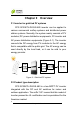

Chapter 2 Overview
6
2.4 Circuit structure design
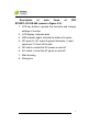
The basic schematic diagram of CPS
SC20KTL-DO/US-480 is shown in Figure 2-2. The input DC
passes through lightning-proof circuit, DC EMI filter, and the
boost circuit to achieve maximum power tracking and boost
up voltages. The inverter converts the DC energy to 3-phase
AC energy. The high frequency components of AC voltage
are removed with a line filter. Then the 3-phase AC energy is
sent through two-stage relays and EMI filter for outputting.
Figure 2-2 Schematic diagram of CPS SC20KTL-DO/US-480
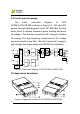
2.5 Appearance description
Figure 2-3 Appearance sketch of CPS SC20KTL-DO/US-480