READ THESE INSTRUCTIONS AND SAVE THEM FOR FUTURE USE . O . F.P t Only en m e lac P r Fo Installation Guide For Models: COL72BP6 COL72ESP6 COL96BP6 COL96ESP6 3170356 Table of Contents: Safety Tips. pg. 1 Unpacking Your Fan. pg. 2 Parts Inventory. pg. 2 Installation Preparation. pg. 3 Hanging Bracket Installation. pg. 3 Fan Assembly. pgs. 4 - 5 Wiring. pg. 6 Canopy Assembly. pg. 7 Blade Assembly. pg. 7 Switch Housing Assembly. pg. 8 Automated Learning Process./ Activating Code. pgs.
SAFETY TIPS. WARNING: To reduce the risk of electrical shock, turn off the electricity to the fan at the main fuse box or circuit panel before you begin the fan installation or before servicing the fan or installing accessories. 1. READ ALL INSTRUCTIONS AND SAFETY INFORMATION CAREFULLY BEFORE INSTALLING YOUR FAN AND SAVE THESE INSTRUCTIONS. CAUTION: To avoid personal injury, the use of gloves may be necessary while handling fan parts with sharp edges. 2. 3. 4.
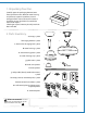
1. Unpacking Your Fan. Carefully open the packaging. Remove items from Styrofoam inserts. Remove motor housing and place on carpet or Styrofoam to avoid damage to finish. Do not discard fan carton or Styrofoam inserts should this fan need to be returned for repairs. Check against parts inventory that all parts have been included. a b 2. Parts Inventory. a. canopy. 1 piece c b. hanging bracket. 1 piece d c. downrod and hanging ball. 1 piece d. motor housing. 1 piece e e. switch housing plate.
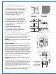
12ft. - 20ft. (3.66m - 6.1m) 3. Installation Preparation. blade edge 30 10 feet inches (3.05m) (76cm) To prevent personal injury and damage, ensure that the hanging location allows the blades a clearance of 10 feet (3.05m) from the floor and 30in. (76cm) from any wall or obstruction. This fan is suitable for room sizes up to 400 square feet (37.2 square meters). 12ft. - 20ft. (3.66m - 6.
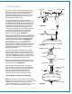
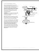
. Fan Assembly. If you wish to extend the hanging length of your fan, you must remove the hanging ball from the downrod provided to use with an extended downrod (sold separately). [If you wish to use the downrod provided, please proceed to instructions following the dotted line below.] To remove hanging ball, loosen set screw on hanging ball, lower hanging ball and remove stop pin.
5. Fan Assembly. (cont.) With the hanging bracket secured to the outlet box and able to support the fan, you are now ready to hang your fan. Grab the fan firmly with two hands. Slide downrod through opening in hanging bracket and let hanging ball rest on the hanging bracket. Turn the hanging ball slot until it lines up with the hanging bracket tab.
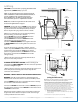
6. Wiring. white supply wire CAUTION: Be sure outlet box is properly grounded or that a ground wire (GREEN or Bare) is present. ground (green or bare) black supply wire Make sure all electrical connections comply with Local Codes or Ordinances and the National Electrical Code. If you are unfamiliar with electrical wiring or if the house/building wires are different colors than those referred to below, please use a qualified electrician.
7. Canopy Assembly. Locate 2 screws on underside of hanging bracket and remove screw closest to the open end of the hanging bracket. Partially loosen the other screw. Lift canopy to hanging bracket. Place rounded part of slotted hole in canopy over loosened screw in hanging bracket and push up. Twist canopy to lock. Re-insert screw that was removed, and then tighten both screws securely.
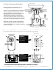
motor housing 9. Switch Housing Assembly. Remove 4 screws from outer edge of switch housing plate (save screws for later use). Remove 1 screw from fitter plate on underside of motor and partially loosen the other 2 screws. Align slotted holes in center of switch housing plate with loosened screws in fitter plate, allowing molex plugs from motor housing to come through hole in middle of switch housing plate. Twist switch housing plate to lock. Re-insert screw that was removed and secure all 3 screws.
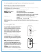
. Automated Learning Process./Activating Code. (cont.) Remove battery cover on back side of remote control transmitter. Install 12-volt battery (provided) in transmitter and wall control. IMPORTANT: Store the transmitter away from excess heat or humidity. To prevent damage to transmitter, remove the battery if not used for long periods.
Troubleshooting. Warranty. WARNING: Failure to disconnect power supply prior to troubleshooting any wiring issues may result in serious injury. CRAFTMADE/ELLINGTON LIFETIME WARRANTY: CRAFTMADE/ELLINGTON warrants this fan to the original household purchaser for indoor use under the following provisions: 1-YEAR WARRANTY: CRAFTMADE/ELLINGTON will replace or repair any fan which has faulty performance due to a defect in material or workmanship.
LEER ESTAS INSTRUCCIONES Y GUARDARLAS PARA UTILIZACION FUTURA . ly O . P . F ent On em c a l P For Guía de instalación Para modelos: COL72BP6 COL72ESP6 COL96BP6 COL96ESP6 3170356 Indice de materias: Sugerencias de seguridad. Pág. 1 Desempaquetado del ventilador. Pág. 2 Inventario de piezas. Pág. 2 Preparación para la instalación. Pág. 3 Instalación del soporte de montaje. Pág. 3 Ensamblaje del ventilador. Págs. 4 - 5 Instalación eléctrica. Pág. 6 Colocación de la cubierta decorativa. Pág.
SUGERENCIAS DE SEGURIDAD. ADVERTENCIA: Para evitar la posibilidad de una descarga eléctrica, desconectar la corriente en la caja de fusibles principal o el interruptor protector antes de iniciar la instalación del ventilador o antes de repararlo o instalar accesorios. 1. LEER TODAS LAS INSTRUCCIONES E INFORMACION DE SEGURIDAD CUIDADOSAMENTE ANTES DE INSTALAR SU VENTILADOR Y GUARDAR ESTAS INSTRUCCIONES.
1. Desempaquetado del ventilador. Abrir el empaque cuidadosamente. Sacar los artículos del embalaje. Sacar el motor y ponerlo en una alfombra o en el embalaje para evitar rayar el acabado. Guardar la caja de cartón o el empaquetamiento original en caso de que tenga que mandar el ventilador para alguna reparación. Comprobar las piezas del ventilador con el inventario de piezas y verificar que se incluyeron todas. 2. Inventario de piezas. a b a. cubierta decorativa. 1 unidad b. soporte de montaje.
3,66m - 6,1m 12 pies - 20 pies 3. Preparación para la instalación. borde del aspa Para prevenir daño corporal y otros daños, estar seguro de que el lugar en donde va a colgar el ventilador le permite un espacio libre de 3,05m (10 pies) entre las puntas de las aspas y el piso y 76cm (30 pulg.) entre las aspas y cualquier pared u otra obstrucción. Este ventilador es adecuado para habitaciones hasta 37,2 metros cuadrados (400 pies cuadrados).
5. Ensamblaje del ventilador. Si usted desea extender la longitud colgante del ventilador, usted tendrá que quitar la bola que sirve para colgar del tubo provisto para usarla con un tubo más largo (a la venta por separado). [Si desea utilizar el tubo provisto, favor de pasar a las instrucciones después de la línea punteada más abajo.
5. Ensamblaje del ventilador. (cont.) bucle del cable de seguridad Ya que esté sujetado el soporte de montaje a la caja de salida y capaz de apoyar el ventilador, usted está listo para colgar el ventilador. Agarrar el ventilador firmemente con las dos manos. Deslizar el tubo por la abertura del soporte de montaje y dejar que se detenga la bola en el soporte de montaje. Girar la bola que sirve para colgar hasta que la ranura de la bola se alinee con la parte saliente del soporte de montaje.
6. Instalación eléctrica. PRECAUCION: Asegurarse de que la caja de salida esté conectada a tierra como es debido o que exista un conductor a tierra (VERDE o pelado). Asegurarse de que toda conexión eléctrica cumpla con los Códigos o las Ordenanzas Locales y el Código Nacional Eléctrico. Si usted no está familiarizado con la instalación eléctrica o los cables de la casa/el edificio son de colores diferentes a los cuales se refieren a continuación, favor de buscar un electricista calificado.
7. Colocación de la cubierta decorativa. Localizar los 2 tornillos en la parte inferior del soporte de montaje y quitar el tornillo que está localizado más cerca del extremo abierto del soporte de montaje. Aflojar parcialmente el otro tornillo. Elevar la cubierta decorativa hasta el soporte de montaje. Poner la parte redondeada del agujero con ranura en la cubierta decorativa encima del tornillo aflojado en el soporte de montaje y empujar hacia arriba. Girar la cubierta decorativa para cerrarla.
9. Instalación de la caja de encendido. bastidor del motor Quitar los 4 tornillos en el borde exterior de la placa de la caja de encendido (guardarlos para uso más adelante). Quitar 1 tornillo de la placa de conexión en la parte inferior del motor y aflojar los otros 2 tornillos.
10. Proceso de aprendizaje automático/Activar el código (cont. ) Quitar la tapa de la batería en la parte de atrás del transmisor del control remoto. Instalar la batería de 12 voltios (incluidas) en el transmisor y el control de pared. IMPORTANTE: Guardar el transmisor lejos del calor excesivo o la humedad. Para prevenir daño al transmisor, sacar la batería si no se va a utilizar el transmisor por un tiempo extendido.
Localización de fallas. Garantía. ADVERTENCIA: El no desconectar el suministro de fuerza eléctrica antes de hacer localización de fallas para cualquier problema de instalación eléctrica puede causar lesiones graves.