
Installation Guide


page 8
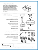
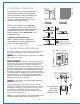
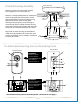
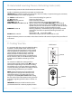
10. Automated Learning Process./Activating Code.
1
4
1
2
12V
1234
D
3
5
6
ON
BACK
FRONT PANEL
SET
ON ECE
IMPORTANT:
Remote and wall
controls must be
SYNCHRONIZED with
fan in order to
properly function.
I
II
IV
VI
III
V
remote control
wall control
5
1234
D
12V
5
ON ECE
ON
6
4
3
1
7
I
OFF ON
II
III
IV
V
VI
2
5
IMPORTANT:
The code switches in
remote and wall
controls MUST MATCH
for fan to function
properly.
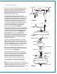
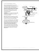
9. Switch Housing Assembly.
Remove 4 screws from outer edge of switch
housing plate (save screws for later use).
Remove 1 screw from fitter plate on underside of
motor and partially loosen the other 2 screws.
Align slotted holes in center of switch housing
plate with loosened screws in fitter plate,
allowing molex plugs from motor housing to
come through hole in middle of switch housing
plate. Twist switch housing plate to lock. Re-insert
screw that was removed and secure all 3 screws.
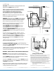
Align holes in switch housing cap with holes in
switch housing plate. Re-insert screws that were
previously removed and use a Phillips screwdriver
to secure all 4 screws.
["Automated Learning Process/Activating Code" continued on next page.]
switch housing
plate
switch
housing cap
molex
plugs
fitter
plate
motor housing