READ THESE INSTRUCTIONS AND SAVE THEM FOR FUTURE USE Installation Guide For Model: SE68SPZ Table of Contents: Safety Tips. pg. 1 Unpacking Your Fan. pg. 2 Parts Inventory. pg. 2 Installation Preparation. pg. 3 Hanging Bracket Installation. pg. 3 Fan Assembly. pgs. 4 - 5 Wiring. pgs. 5 - 6 Canopy Assembly. pg. 6 Scroll Arm Assembly. pg. 7 Blade Assembly. pg. 7 Switch Housing Assembly. pg. 8 Automated Learning Process./ Activating Code. pg. 9 Wall Control Operation. pg. 10 Remote Control Operation. pg.
SAFETY TIPS. WARNING: To reduce the risk of electrical shock, turn off the electricity to the fan at the main fuse box or circuit panel before you begin the fan installation or before servicing the fan or installing accessories. 1. READ ALL INSTRUCTIONS AND SAFETY INFORMATION CAREFULLY BEFORE INSTALLING YOUR FAN AND SAVE THESE INSTRUCTIONS. CAUTION: To avoid personal injury, the use of gloves may be necessary while handling fan parts with sharp edges. 2. 3. 4.
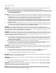
1. Unpacking Your Fan. Carefully open the packaging. Remove items from Styrofoam inserts. Remove motor housing and place on carpet or Styrofoam to avoid damage to finish. Do not discard fan carton or Styrofoam inserts should this fan need to be returned for repairs. Check against parts inventory that all parts have been included. a 2. Parts Inventory. c b L1 L2 a. hanging bracket. 1 piece b. remote control transmitter and plate. 2 separate pieces e d c. remote control receiver.
To prevent personal injury and damage, ensure that the hanging location allows the blades a clearance of 7 feet (2.13m) from the floor and 30in. (76cm) from any wall or obstruction. This fan is suitable for room sizes up to 400 square feet (37.2 square meters). This fan can be mounted with a downrod on a regular (no-slope) or vaulted ceiling. The hanging length can be extended by purchasing a longer downrod (0.5in./1.27cm diameter). Other installation, such as flushmount, is not available for this fan.
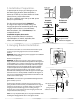
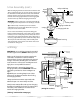
. Fan Assembly. If you wish to extend the hanging length of your fan, you must remove the hanging ball from the 8in. downrod provided to use with an extended downrod (sold separately). [If you wish to use the 8in. downrod, please proceed to instructions following the dotted line below.] set screw hole set screw stop pin hanging ball To remove hanging ball, loosen set screw on hanging ball, lower hanging ball and remove stop pin.
5. Fan Assembly. (cont.) With the hanging bracket secured to the outlet box and able to support the fan, you are now ready to hang your fan. Grab the fan firmly with two hands. Slide downrod through opening in hanging bracket and let hanging ball rest on the hanging bracket. Turn the hanging ball slot until it lines up with the hanging bracket tab.
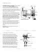
6. Wiring. (cont.) IN ORDER TO WIRE WALL CONTROL, remove existing wall switch. Wire the WALL CONTROL with wire connectors provided as shown in diagram at right. outlet box * Wrap each wire connector separately with electrical tape as an extra safety measure. Gently push wires and taped wire connectors into outlet box. Use a ballpoint pen or a small screwdriver to set the code switches 1 through 4 on the wall control. Factory setting is pre-set and not recommended for use.
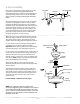
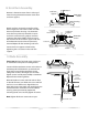
. Scroll Arm Assembly. downrod scroll arm support Remove 3 decorative screws from inside top of motor housing. Remove decorative screws from scroll arm support. decorative screws motor housing Attach scroll arm to motor housing first. Align hole in larger end of one of the scroll arms with hole in top of motor housing--use decorative screw that was previously removed to secure scroll arm to motor housing.
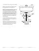
10. Switch Housing Assembly. motor housing Remove 3 screws from outer edge of switch housing plate (save screws for later use). Remove 1 screw from fitter plate on underside of motor and partially loosen the other 2 screws. Align slotted holes in center of switch housing plate with loosened screws in fitter plate, allowing male plug from motor housing to come through hole in middle of switch housing plate. Twist switch housing plate to lock. Re-insert screw that was removed and secure all screws.
11. Automated Learning Process./Activating Code. CAUTION: The remote control transmitter can be programmed to multiple receivers or fans. If this is not desired, turn wall switch off to any other programmable receiver or fan. TRANSMITTER (front) L1 L2 This remote control transmitter is equipped with 16 code combinations to prevent possible interference from or to other remote units such as garage door openers, car alarms or security systems.
12. Wall Control Operation.
14. Testing Your Fan. It is recommended that you test fan before finalizing installation. Locate ON/OFF slider switch on wall control and set to the ON position. Test light and dimmer functions with the L1 and L2 light buttons and then test fan speeds with different fan speed control buttons on the wall control. Next, locate remote control transmitter. Test fan speeds with the different fan speed buttons on remote control.
Troubleshooting. Warranty. Warning: Failure to disconnect power supply prior to troubleshooting any wiring issues may result in serious injury. CRAFTMADE/ELLINGTON LIFETIME WARRANTY: CRAFTMADE/ELLINGTON warrants this fan to the original household purchaser for indoor use under the following provisions: 1-YEAR WARRANTY: CRAFTMADE/ELLINGTON will replace or repair any fan which has faulty performance due to a defect in material or workmanship.