
Table Saw Operator's Manual


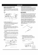


BLADE GUARD ASSEMBLY (FIG. K, L, M)
1. Set the blade to maximum height and the tilt to
zero degrees on the bevel scale with the hand
wheels. Lock the blade lock knob.
2. Place the external toothed lock washer (1) ,a steel
flat washer (2) and a spring washer (10) onto the
long hex head bolt (3). Insert the bolt into the
splitter bracket (4) as shown. (Fig. K)
Fig. K
1
10 3
[,l'kWARNING I
Improper splitter alignment can cause
"kickback" and serious injury,
Anti-kickback pawl
8 Fig. M
3. Place the oval washer (5) on the pivot rod (6). (Fig.
L)
4. Install the bracket assembly (4) at the rear of the
saw table and snugly - do not tighten. Thread the
bolt (3) into the internally threaded pivot rod.
NOTE: The splitter is removed from the illustration
for clarity.
Fig. L
6 5
5. Raise the blade to the maximum height. (Fig. M)
6. Using a straight edge, check to see if the blade
guard splitter (8) is aligned with the saw blade (9).
Make sure the straight edge lies between the
teeth of the blade when aligning.
7. If straightening adjustment is necessary, loosen
the bolt (3) and shift the splitter assembly to right
or left for proper alignment.
8. When the splitter is properly aligned with the saw
blade, tighten the bolt, very tight.
9. If height adjustment is necessary, loosen the knob
(11 ) and raise the splitter assembly to the desired
height and tighten the knob. (Fig. K)
NOTE: The splitter must always be correctly
aligned so that the cut workpiece will pass on
either side without binding or twisting to the side,
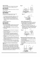
INSTALLING TABLE SIDE EXTENSIONS (FIG. N)
1. Identify the right hand table extension.
NOTES:
For illustration purposes the view in Fig. N looks
"through" the saw table to the under side of the
table.
The right hand table extension is the one with
the measuring scale (1) visible from the front of
the saw when it is installed to the right hand side
of the saw table (Fig. N).
2. Unlock both front and rear cam locking levers (2)
on the right hand side of the saw base.
3. Insert the table extension mounting tubes (3)
into the two matching holes in the cam lever
assemblies.
NOTE: Make sure the front mounting tube has
the measuring scale visible from the front of the
saw.
4. Slide the table extension toward the table until it
rests against the saw table.
5. Place the location seat on the rear side
extension tube.
6. Lock both cam locking levers.
Fig. N