
Table Saw Operator's Manual


BASIC SAW OPERATIONS
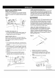
RAISE THE BLADE (FIG. T)
To raise or lower the blade, turn the blade elevation
handwheel (1) to the desired blade height, and then
tighten lock handle (2) to maintain the desired blade
angle.
Fig. T
1 2
TILTING THE BLADE (FIG. T)
1. To tilt the saw blade for bevel cutting, loosen the
lock knob (2) and turn the tilting handwheel (3).
2. Tighten the lock knob (2) to secure.
ON/OFF SWITCH (FIG. U)
The ON / OFF switch has a removable safety key.
With the key removed from the switch, unauthorized
and hazardous use by children and others is
minimized.
1. To turn the saw ON, insert key (1) into the slot in
the switch (2). Move the switch upward to the ON
position.
2. To turn the saw OFF, move the switch downward.
3. To lock the switch in the OFF position, grasp the
sides (or yellow part) of the switch toggle (1), and
pull it out.
4. With the switch key removed, the switch will not
operate.
5. If the switch key is removed while the saw is
running, it can be turned OFF but cannot be
restarted without re-inserting the switch key (t).
Fig. U
3
OVERLOAD PROTECTION (FIG. U)
This saw has an overload relay button (3) that resets
the motor after it shuts off due to overloading or low
voltage. If the motor stops during operation, turn the
ON / OFF switch to the OFF position. Wait about five
minutes for the motor to cool. Push in the reset
button (3) and turn the switch to the ON position.
I_, WARNING]
To avoid injury, the ON / OFF switch should be in the
OFF position and the plug removed from the power
source while the cool down takes place, to prevent
accidental starting when the reset button is pushed.
Overheating may be caused by misaligned parts or a
dull blade or undersized extensing cord. Inspect your
saw for proper setup before using it again.
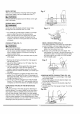
USING THE TABLE EXTENSION (FIG. V, V-l)
If the table extension is not parallel with the table.
Remove the bolts (1) and position the parallel
washers (2) between the table extension and tube
until it is parallel with the table, then tighten the bolts.
NOTE: Parallel washer (2) see page 6 for table of
loose parts ITEM: W-2
Fig. V
j_
1. Release the extension lock handles.
2. Slide the extension out until the correct
measurement is displayed on the tube scale.
The user sights the scale off the edge of the
table.
3. Tighten all extension lock handles.
Fig. V-1