Operator's Manual 1/2 in., 19.2 VOLT CORDLESS Variable Speed / Reversible DRILL-DRIVER Model No. 315.114850 WARNING: To reduce the risk of injury, the user must read and understand the operator's manual before using this product. Customer Help Line: 1-800-932-3188 Sears, Roebuck and Co., 3333 Beverly Rd., Hoffman Visit the Craftsman web page: www.sears.
• Warranty ........................................................................................................................................................................... 2 • Introduction ...................................................................................................................................................................... 2 • General Safety Rules .................................................................................................................
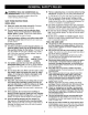
_k • WARNING: READ AND UNDERSTAND ALL INSTRUCTIONS. Failure to follow all instructions listed below, may result in electric shock, fire and/or serious personal injury. SAVE THESE WORK AREA Keep your work area clean and well lit. Cluttered benches and dark areas invite accidents. • Do not operate power tools in explosive atmospheres, such as in the presence of flammable liquids, gases, or dust. Power tools create sparks which may ignite the dust or fumes.
SERVICE • Toolservicemust • When parts. of this follow shock • • Do not place battery tools or their batteries near fire or heat. This will reduce the risk of explosion and possibly injury. • Batteries vent hydrogen gas and can explode in the presence of a source of ignition, such as a pilot light. To reduce the risk of serious personal injury, never use any cordless product in the presence of open flame. An exploded battery can propel debris and chemicals. If exposed, flush with water immediately.
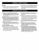
• _IL WARNING? Read and understand all instructions. Failure to follow all instructions listed below, may result in electric shock, fire and/or serious peronal injury. • • lutely necessary. Use of improper extension cord could result in a risk of fire and electric shock.
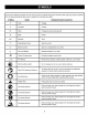
Some of the following symbols may be used on this tool. Please study them and learn their meaning. Proper interpretation of these symbols will allow you to operate the tool better and safer.
The following signalwordsand meaningsare intendedto explainthe levelsof risk associatedwith this product. SYMBOL SIGNAL MEANING DANGER: Indicates an imminently hazardous situation, which, if not avoided, will result in death or serious injury. WARNING: Indicates a potentially hazardous situation, which, if not avoided, could result in death or serious injury. CAUTION: Indicates a potentially hazardous situation, which, if not avoided, may result in minor or moderate injury.
SPECIFICATIONS Chuck ............................................................................................................................................................... Motor ................................................................................................................................................................... 1/2 in. Keyless 19.2 Volt DC Switch ...........................................................................................................................
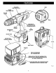
TWO-SPEED GEARTRAIN (HI-LO) LEVEL TORQUE ADJUSTMENTRING KEYLESS CHUCK LEVEL REARVIEW DIRECTIONOF ROTATIONSELECTOR (FORWARD/REVERSE) SWITCH TRIGGER BIT STORAGE SCREWDRIVER BITS BATTERYPACK BATTERYPACK SHOWNIN CHARGER 4-1/2 in. WRIST STRAP CHARGER RED LEDON INDICATES FASTCHARGINGMODE GREENLED ONAFTERFASTCHARGINGCYCLE, INDICATESFULLYCHARGEDBATTERYPACK AND IN TRICKLECHARGEMODE. YELLOWANDGREENLEDS ON INDICATESDEEPLY DISCHARGEDOR DEFECTIVEBATTERYPACK. Fig.
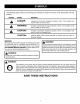
INSTRUCTIONS PACKING When unpacking the tool: 112 in. Drill • Carefully box. • Make sure that all items listed in the packing list are included. • Inspect the tool carefully to make sure no breakage or damage occurred during shipping. Case • Do not discard the packing material until you have carefully inspected and satisfactorily operated the tool.
LED FUNCTIONS WARNING: Do not allow familiarity with tools make you careless. Remember that a careless fraction of a second is sufficient to inflict severe injury. LED WILL CHARGER OF CHARGER BE ON TO INDICATE STATUS AND BATTERY PACK: OF • Red LED on = Fast charging mode. • Green LED on = Fully charged and in trickle charge mode. • Note: Batteries will not reach full charge the first time they are charged. Allow several cycles (drilling followed by recharging) for them to become fully charged.
SWITCH TO INSTALL See Figure 2. • To turn your drill ON, depress the switch trigger. To turn it OFF, release the switch trigger. • FORWARD/REVERSE SELECTOR VARIABLESPEED SWITCHTRIGGER VARIABLE BATTERY PACK Lock switch trigger on your drill by placing the direction of rotation selector in center position. See Figure 5. Place battery pack in your drill. Align raised rib on battery pack with groove inside drill. See Figure 4. BATTERY Fig.
SWITCHLOCK KEYLESS See Figure 5. See Figure 6. The switch trigger can be locked in the OFF position. This feature can be used to prevent the possibility of accidental starting when not in use. To lock switch trigger, place the direction of rotation selector (Forward/Reverse Selector) in center position. Your drill has a keyless chuck. As the name implies, you can hand tighten or release drill bits in the chuck jaws. Grasp and hold the collar of the chuck with one hand.
INSTALLING BITS REMOVING BITS See Figure 7. See Figure 7. • Lock the switch trigger by placing the direction of rotation selector in center position. See Figure 5. • Lock the switch trigger by placing the direction of rotation selector in center position. See Figure 5. • Open or close chuck jaws to a point where the opening is slightly larger than the bit size you intend to use. Also, raise the front of your drill slightly to keep the bit from falling out of the chuck jaws.
LEVEL BIT STORAGE See Figure 10. When not in use, bits provided with your drill can be placed in the storage area located on the bottom of your drill as shown in figure 10. SCREWDRIVER BIT BIT STORAGEAREA ,_ Fig. 1 O WARNING: Always wear safety goggles or safety glasses with side shields when operating tools. Failure to do so could result in objects being thrown into your eyes, resulting in possible serious injury. Fig. 12 LEVEL DRILLING See Figure 11. See Figure 12.
CHUCK REMOVAL • See Figures 13, 14, and 15. • Lock the switch trigger by placing the direction of rotation selector in center position. See Figure 5. • Insert a 5/16 in. or larger hex key into the chuck of your drill and tighten the chuck jaws securely. • Tap the hex key sharply with a mallet in a clockwise direction. See Figure 13. This will loosen the screw in the chuck for easy removal. Insert hex key in chuck and tighten chuck jaws securely.
Do not abuse power tools. Abusive practices can damage tool as well as workpiece. WARNING: When servicing, use only identical Craftsman replacement parts. Use of any other part may create a hazard or cause product damage. Only the parts shown on parts list, page 19, are intended to be repaired or replaced by the customer. All other parts should be replaced at a Sears Service Center. Avoid using solvents when cleaning plastic parts.
CRAFTSMAN 1/2 in., 19.2 VOLT CORDLESS DRILL-DRIVER - MODEL NO. 315.114850 The model number will be found on a plate attached to the motor housing. Always mention the model number in all correspondence regarding your 1/2 in., 19.2 VOLT CORDLESS DRILL-DRIVER or when ordering repair parts. i SEE BACK PAGE FOR PARTS ORDERING INSTRUCTIONS 2 4 3 \ PARTS LIST Key No. Part Number Description 1 6613402 Screw (Special) .................................................................................