
Operator`s manual


A WARNING:WhenservicinguseonUyidenficaU
CraftsmanrepUacementparts.Useofanyother
partsmaycreatea hazardorcauseproduct
damage.
GENERAL
AvoidusingsoUventswhenchartingpUastbparts.
MostpUastbsaresuscepfiMetodamagefromvarious
typesofcommerdaUsoUventsandmaybedamaged
bytheiruse.Usedeanclothstoremovedirt,carbon
dust,etc.
,_ WARNmNG: Do not at any time Uetbrake fluids,
gasoline, petrobum-based products, penetrating
oils, etc. come in contact with pUastb parts. They
contain chemicaB that can damage, weaken, or
destroy pUasfic.
LUBRICATION
AH of the bearings in this tooUare Uubrbated with a
sufficient amount of high grade hJbricant for the life of
the unit under normal operating conditions. Therefore,
no further hJbrication is required.
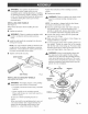
REPLACmNG GUARD
See Figure 9.
After extended use, the guard may wear and need
replacing. If you drop your grinder and damage the
guard it may also be necessary for you to replace it.
Follow these directions when replacing the guard.
[] Unplug your grinder.
,A WARNING: Failure to unplug your grinder could
result in accidental starting causing serious
[] Depress spindle lock button and rotate clamp nut
until spindle locks.
[] Loosen and remove clamp nut from spindle using
the wrench provided.
[] Remove grinding wheel and disc flange.
[] Loosen the clamp screw until you can remove the
guard from the bearing cap.
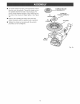
[] Place the new guard on the shoulder of the
bearing cap.
NOTE: If the new guard will not fit, loosen the
clamp screw until they slide over the bearing cap.
[] Rotate guard to the correct position as shown.
NOTE: Be sure the raised ridge on the guard is
seated in the groove on the bearing cap.
TO
TIGHTEN
WRENCH
CLA_IP
GRINDING
WHEEL
DISC
FLANGE
GUARD
CLAMP
SCREW
SPINDLE
BEARINGCAP FLATS
Fig. 9
[] Tighten clamp screw securely.
[] Reassemble disc flange, grinding wheel, and
clamp nut. Refer to °qnstalling Accessory
Wheels" earlier in this manual.
[] Tighten the clamp nut securely with the wrench
provided.
14