Product Manual Router Table Model No. 320. 28180 CAUTION! Read, understand and follow all Safety Rules and Operating Instructions in this Manual before using this product. • Warranty • Safety • Assembly ° Operation o Maintenance Sears, Roebuck and Co., Hoffman Estates, IL 60179 www.craftsman.
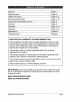
Warranty Page 2 Safety Symbols Page 3-4 Safety Instructions Page 5-10 Know Your Router Table Page 11-12 Unpacking and Checking Contents Page 12 Parts list Page 13 Assembly Page 14-17 Operation Page 17-21 Maintenance Pages 22 Troubleshooting Pages 22 ONE YEAR FULL WARRANTY ON CRAFTSMAN® TOOL If this Craftsman tool fails to give complete satisfaction within one year from the date of purchase, return it to any Sears store or parts & repair center or other Craftsman outlet in the United
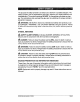
The purpose of safety symbols is to attract your attention to possible dangers. The safety symbols, and the explanations with them, deserve your careful attention and understanding. The symbol warnings DO NOT, by themselves, eliminate any danger. The instructions and warnings they give are no substitutes for proper accidentprevention measures. _, WARNING= BE SURE to read and understand all safety alert symbols, such as "DANGER," "WARNING," and "CAUTION" BEFORE using this product.
Some of these following symbols may be used on this tool. Please study them and learn their meaning, Proper interpretation of these symbols will allow you to operate the tool better and more safely.
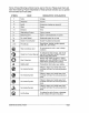
WARNING: READ AND UNDERSTAND ALL INSTRUCTIONS. Failure to fol- low all instructions listed below and the instructions in the product manual for your router may result in serious personal injury. WORK AREA SAFETY • Keep the work area clean and well lit. Cluttered invite accidents. benches and dark areas Don't use in a dangerous environment. Don't use power tools in damp or wet locations or expose them to rain.
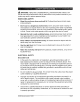
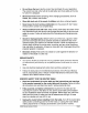
o Use only 3-wire extension cords that have 3-prong pole receptacles that accept the tool's plug. o Repair or replace a damaged Repair or replace damaged grounding plugs and 3- or worn cord immediately. or worn cord immediately. This tool is intended for use on a circuit that has an outlet that looks like the one illustrated in Sketch A in the figure below. The tool has a grounding plug that looks like the plug illustrated in sketch A in the figure below.
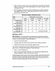
Table A shows the correct size to use, depending on cord length and ampere rating. If in doubt, use the next heavier gauge: the smaller the gauge number, the heavier the cord. When operating a power tool outdoors, ALWAYS use an outdoor extension cord marked "W-A" or "W." These cords are rated for outdoor use and reduce the risk of electric shock. Minumum Gauge for Extension Cords Volts Total Length of Cord in Feet 0-25ft. 25-50_. 51-100ff. 101-150_.
,_ WARNING: The operation of any power tool can result in foreign objects be- ing thrown into your eyes, which can result in severe eye damage. Before beginning power-tool operation, always wear safety goggles or safety glasses with side shields, and a full-face shield when needed. We recommend Wide Vision Safety Mask for use over eyeglasses or standard safety glasses with shields. Always use eye protection that is marked to comply with ANSI Z87.
O Do not force the tool, Use the correct tool and blade for your application. The correct tool and cutter will do the job better and more safely at the rate for which it is designed. o Disconnect tools before servicing; when changing blades, bits, cutters, and the like. o Store idle tools out of the reach of children and other untrained people. o Never leave the tool running unattended; the tool until it comes to a complete stop.
Do not plug the router power cord into a wall outlet. It must be plugged into the router table switch. Power tool switches and controls need to be within your reach in emergency situations° Before operating, make sure that the entire unit (table with router installed) is placed on and secured to a solid, flat, level surface and that it will not tip. Use of auxiliary infeed and ouffeed supports is necessary for long or wide work pieces.
Your router table has a precision-built electric switch box and it should be connected to only a 120-volt, 60-HZ AC power supply (normal household current), DO NOT operate on direct current (DC). The large voltage drop would cause a loss of power and the motor would overheat. If the router table does not operate when plugged into correct 120-volt, 60-HZ AC ONLY outlet, check the power supply° The router table comes with an 8-ft. power cord (no adapter needed).
9, Integrated switch shield prevents dust from accumulating 10. Dust Collection/Guard in the sockets. reduces dust dispersal, 11. Above-the-table height adjustment: the bit height can be adjusted by turn.. ing the adjustment knob clockwise or counterclockwise with a hex wrench (5 inches long and 5mm in diameter, not included). This feature functions only when using the Craftsman router supplied with this table (model 17541) or the following Craftsman routers: models 17542 and 17543.
Description Key NO.
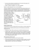
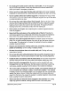
ATTACHING . THE LEGS TO THE TABLE TOP Place the router table Fig, 2 surface upside down on a flat, level surface, with the underside of the table facing up. , Position the legs relative to the router table as shown in Fig, 2. Position one short end of the table so that it extends beyond the edge of your work surface far enough to gain access to the four holes in that end of the 3_ router-table , . top. Align the two outermost holes on the table top with the holes in the leg bracket.
ATTACHING THE ROUTER TO THE TABLE Fig. 4 Attach the router to the router table after you have assembled the table. Place the router table upright, with the front edge closest to you. Be sure that the table is stable and that it rests on 2_ all four legs, . Remove the sub-base from the fixed-based router supplied. 4_ 5. Hold the router upside down, and align the three holes in the center of the table with the holes in the router, as shown in Fig° 4.
ATTACHING THE FENCE TO THE TABLE (Fig. 6) Fig. 6 ,_ WARNING" Always unplug the router before attaching or removing the fence° The fence has been shipped completely assembled. 1. Place the fence assembly on the table with the four wing nuts facing toward you. = Align the two holes on the bottom of fence assembly with the two channels on the router table. Secure the fence to the 3_ Fig. 7 table with two clamping knobs (5), two plain washers (11), and two short, roundhead, square-neck bolts (6).
= 5. . Drill a hole at each of the marked locations. Place the router table on the work surface, legs with the holes in the work surface. and align the holes in the table Secure the router table to the work surface using four screws (not supplied). 7_ Securely tighten the screws° SWITCH OPERATION The switch has a safety key to help prevent accidentally switching and the unauthorized, possibly hazardous use by others° The safety key must be completely can be turned ON.
3. To turn the router OFF, push the ON/OFF switch down. (Fig, 11) Fig. 11 WARNING: Never leave the router unattended while it is running or before it comes to a complete stop. , To lock switch in the OFF position, push the ON/ OFF switch down to turn the switch OFF, and remove the safety key from the switch. Two receptacles are located at the back of the switch assembly (Fig. 12). Use one for plugging in the router. The other may be used to plug in a vacuum or a light (not included).
ADJUSTING THE FENCE Fig_ 13 The fence enables you to support and guide the work piece,. To adjust the extended fence forward and backward (Fig, 13) 1. Loosen the two clamping knobs (5). 2. Move the fence forward or backward along the slots to the desired position, 3, Tighten the clamping knobs.The fence can be moved forward and backward 3-3/4 in. Fig, 'I 4 To laterally adjust the infeed and ouffeed fence The infeed and outfeed fence can each be adjusted 2 inches in order to lengthen the fence° 1.
ADJUSTING THE MITER GAUGE (Fig. 16) 1, Loosen the miter gauge knob, 2, Rotate the miter gauge to the desired angle. 3, Tighten the miter gauge knob. Fig. 16 ADJUSTING THE CUTTING HEIGHT NOTE: This method of cutting height adjustment is applicable only to the fixed-base router supplied with this router table or other Craftsman routers with the following model numbers: 17542 and 17543. NOTE." A hex wrench 5 inches long and 5mm in diameter is required for this operation (not included).
USING THE ROUTER WITH THE ROUTER TABLE 1. Read the and understand entire Product Manual for the router, 2. Always plug the router into the switched outlet in the router table° Never plug a router-table-mounted router into another power source. 3. Make sure the router-table 4. Plug the router-table switch is off. Lock-on the router switch. cord into a power source° 5_ Turn on the power to the router table by pulling out the ON/OFF switch. 6.
GENERAL ,_ MAINTENANCE WARNING" Avoid using solvents when cleaning plastic parts. Most plastics are susceptible to damage from various types of commercial solvents and may be damaged by their use. Use clean cloths to remove dirt, dust, oil, grease, etc. ,_ WARNING; Do not at any time let brake fluids, gasoline, petroleum-based products, penetrating oils, etc., come in contact with plastic parts. Chemicals can damage, weaken or destroy plastic, which may result in serious personal injury.
28180 Manual_Revlsed_07-0228 Page 23
Get it fixed, at your home or ours! i ¸ Your Home For repair- in your home - of all major brand appliances lawn and garden equipment or heating and cooling systems no matter who made it, no matter who sold it! For the replacement parts, accessories and owner's manuals that you need to do-it-yourself For Sears professional installation of home appliances and items like garage door openers and water heaters. 1-800-4-MY-HOME ® (I-800-469-4663) www.sears.