Operator's Manual ® Chip-N-Vac Model No's. 486.25013 STOP DO NOT RETURN TO STORE For Missing Parts or Assembly Questions Call 1-866-576-8388 IMPORTANT: The engine is shipped without oil. Add oil before starting the engine. IMPORTANT: The wheel bearings are not pre-lubricated. Fill the wheel hubs with grease after assembling the wheels to the axle. CAUTION: Before using this product, read this manual and follow all Safety Rules and Operating Instructions.
TABLE OF CONTENTS WARRANTY................................................................. 2 SAFETY RULES........................................................... 3 FULL SIZE HARDWARE CHART................................. 6 CARTON CONTENTS.................................................. 7 ASSEMBLY................................................................... 8 OPERATION............................................................... 16 MAINTENANCE...................................................
SAFETY Any power equipment can cause injury if operated improperly or if the user does not understand how to operate the equipment. Exercise caution at all times, when using power equipment. • Read and follow all instructions in this manual before attempting to assemble or operate this equipment. Failure to comply with these instructions may result in personal injury. Keep this manual in a safe place for future reference and for ordering replacement parts.
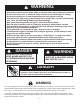
WARNING TO AVOID SERIOUS INJURY • • • • • • • • • • • • • Read Owner's Manual and all safety labels on machine before starting and using machine. Do Not remove top cover or attempt to empty contents of cart while engine is running. Do Not stand behind cart in exhaust discharge area while engine is running. Keep hands, feet, face, long hair and clothing out of chipper inlet, vac inlet, and discharge area. There are ROTATING BLADES inside these openings. Wear approved safety glasses and gloves.
ACCESSORIES AND ATTACHMENTS These accessories were available when the unit was purchased. They are also available at most Sears retail outlets and service centers. Most Sears stores can order repair parts for you when you provide the model numbers of your tractor and Chipper Vac System. The Hand Wand Attachment, Model 486.24509 provides a 12' x 5" diameter hose to clean around shrubs, patios, window wells and other areas not accessible to the tractor.
HARDWARE PACKAGE CONTENTS SHOWN FULL SIZE A B C D E F G L I O N K H M J T S P R Q U NOT SHOWN FULL SIZE BB V W X Y Z CC DD AA EE See page 14 for the Deck Adapter hardware package. (Contents not included here.) REF. A B C D E F G H I J K L M N O P PART QTY NO. CART VAC 43574 3 — 43351 — 1 43087 2 — 1509-90 — 5 43661 — 2 43182 — 6 43012 — 14 43866 9 20 47630 — 4 43814 12 — 1543-69 — 6 43088 2 36 43081 — 3 43352 — 1 43601 4 — 47189 9 40 DESCRIPTION REF.
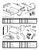
1 4 3 2 7 6 5 8 9 10 CARTON CONTENTS (Cart Body Carton) REF. PART NO. 1 23507 2 63917 3 63155 4 49974 5 23985 QTY 1 1 1 1 2 DESCRIPTION Wheel Support Rear Tongue Front Tongue Hose Hanger Rod Cart Body REF. PART NO. 6 41882 7 62458 8 24897 9 24497 10 42159 2 1 3 QTY 1 1 1 1 2 DESCRIPTION Hose Tailgate Reinforcement Bracket Axle Latch Stand Bracket Wheels 4 5 7 6 12 11 9 13 8 10 CARTON CONTENTS (Mow-N-Vac Carton) REF.
ASSEMBLY This unit is shipped WITHOUT GASOLINE or OIL. After assembly, see separate engine manual for proper fuel and engine oil recommendations. • TOOLS REQUIRED FOR ASSEMBLY (1) Screwdriver (1) Pliers (2) 7/16" Wrenches (2) 1/2" Wrench (2) 9/16" Wrenches (2) 3/4" Wrenches (only if figure 23 on page 12 is used) • 1/4" NYLOCK NUT REMOVAL OF PARTS FROM CARTONS • • • 1/4" x 5/8" HEX BOLT Remove the hardware packs and all loose parts from the cartons.
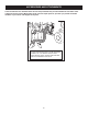
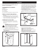
• Assemble the wheel support to the bottom of the cart using eight 5/16" x 3/4" truss head bolts and 5/16" nylock nuts as shown in figure 4. Heads of bolts go on the inside of cart. Tighten. • Position the rear tongue on the wheel support and the latch stand bracket. Assemble the axle through the wheel support and the tongue. See figure 6. IMPORTANT: Make sure the tongue is securely locked to the latch stand bracket by the latch lock lever.
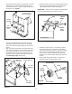
• ASSEMBLING VAC PARTS Flip the cart over so that it rests on its wheels. • Assemble the front tongue on top of the rear tongue using three 3/8" x 3" hex bolts and 3/8" nylock nuts. See figure 8. HINT: For easier assembly, support the rear tongue with a block of wood. 3/8" x 3" HEX BOLT • Release the latch lock lever and tilt the cart bed back. See figure 10. • Assemble the front panel to the cart bed, sliding the bottom lip of the panel in between the cart bed and the latch stand bracket.
• • Place a side panel on top of the cart bed flange, inside the lip of the front panel. Fasten the side panel to the front panel using three 1/4" x 5/8" hex bolts and 1/4" nylock nuts. Fasten the side panel to the cart bed flange using two 1/4" x 5/8" hex bolts, 1/4" flat washers and 1/4" nylock nuts. Tighten. See figure 11. Repeat on other side. Assemble a door latch at each end of the cross brace using a 5/16" x 3/4" hex bolt, a nylon washer and a 5/16" nylock nut.
• • • Assemble a short tarp strap to rear door using one 1/4" x 1-1/4" hex bolt, two 1/4" flat washers and one 1/4" nylock nut. Assemble an "S" hook through loose end of strap. See figure 15. Repeat on other side of door. Assemble door to rear of cart by resting bottom of door on door supports and pushing top of door in against cross brace. Secure top of door using door latches on each side. See figure 15. Hook both the tarp straps onto the 1/4" x 1" hex bolts in the sides of the cart. See figure 15.
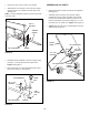
• HINT: Tip the cart bed back for easier access in the next paragraph. •. Attach the chipper chute assembly to the weld bolts on the back side of the impeller housing using three 5/16" flat washers and 5/16" Nylock nuts. Tighten. See figure 20. • Insert the tamper plug into the end of the chipper chute assembly. Assemble the hose adapter (nozzle) to the front of the impeller housing and secure with the three knobs. Make sure that the switch actuator bracket contacts the switch on the housing.
BEFORE PROCEEDING, look in the fold-out sheets included with this manual to find templates for Sears mower decks. If written instructions are printed on the template, follow those instructions instead of the instructions in this manual. STOP ASSEMBLING THE DECK ADAPTER (#62468) TO THE MOWER DECK • Remove the mower discharge deflector from your mower deck. Save the deflector and hardware for remounting deflector.
• Position the adapter over the deck opening, and check for fit of cutout as shown in figure 24. Trim cutout, if necessary, to allow tilting of adapter, keeping the fit as close as possible for best vacuum suction. • Assemble the adapter bracket to the deck using two 5/16" x 1-1/4" hex bolts, 5/16" flat washers and 5/16" nylock nuts. See figure 26. NOTE: It may be necessary to use extra 5/16" flat washers to shim under the bracket next to the deck surface.
OPERATION HOW TO USE YOUR CHIP-N-VAC BEFORE STARTING • • • CAUTION: Vehicle braking and stability may be affected with the addition of an accessory or an attachment. Be aware of changing conditions on slopes. Your Chip-N-Vac engine is shipped without oil or gasoline. Service the Chip-N-Vac engine with oil and gas as instructed in the separate engine manual. Inspect the Chip-N-Vac to make sure all covers (rear door, vinyl boot, elbow, hose adapter, hose and deck adapter are properly attached.
USING THE CHIPPER CHUTE • • • • Material such as stalks or heavy branches up to 3" in diameter may be fed into the chipper chute as shown in figure 29. Be sure to wear eye protection and gloves when feeding material into the chipper chute. Use the tamper plug, not your hands, to force material down through the chipper chute. For best performance, it is important to keep the chipper blades sharp. If the composition of the material being discharged changes (becomes stringy, etc.
MAINTENANCE CUSTOMER RESPONSIBILITIES • Read and follow the maintenance schedule and the maintenance procedures listed in this section. MAINTENANCE SCHEDULE Fill in dates as you complete regular service. se e e n h u h us aso orag c a ac e st e s e e e y for ter ver efor E Be Af B Service Dates Check for loose fasteners X Check soft vinyl boot X Check tire pressure X Check engine oil level X Lubricate X Clean X X Maintain engine per instructions below and in engine manual.
SERVICE AND ADJUSTMENTS SHARPENING OR REPLACING CHIPPER BLADES • • • • • NYLOCK NUTS Disconnect the spark plug wire and move wire away from the spark plug. Remove the access plate by removing two hex lock nuts. See figure 30. Locate one of the chipper blades in the access plate opening by rotating the impeller assembly by hand. Remove the blade using a 3/16" allen wrench on the outside of the blade and a 1/2" wrench on the impeller assembly, inside the housing.
TROUBLESHOOTING PROBLEM POSSIBLE CAUSE(S) CORRECTIVE ACTION Engine fails to start 1. Spark plug wire disconnected. 2. Safety switch not contacted. 3. Fuel tank empty, or stale fuel. 4. Fuel shut-off valve closed (if so equipped). 5. Faulty spark plug. 1. Connect wire to spark plug. 2. Correctly install hose adapter nozzle. 3. Fill tank with clean, fresh fuel. 4. Open fuel shut-off valve. 5. Clean, adjust gap or replace. Loss of power; operation erratic. 1. Spark plug wire loose 2.
NOTES 21
NOTES 22
PARTS REPAIR PARTS FOR MODEL 486.25013 Chip-N-Vac IMPELLER HOUSING ASSEMBLY 12 A 2 11 A 13 1 11 13 12 23 28 11 1 15 28 3 5 6 8 10 8 9 4 12 20 27 7 22 18 5 14 19 28 17 16 25 26 REF. PART NO. QTY. DESCRIPTION 1 23985 2 Cart Body 2 62458 1 Tailgate Reinforcement Bracket 3 23507 1 Wheel Support 4 24497 1 Latch Stand Bracket 5 24897 1 Axle, Wheel 1" Dia. 6 42159 2 Wheel w/Tire, 15 x 6.00 7 43093 2 Cotter Pin, 1/8" Dia.
REPAIR PARTS FOR MODEL 486.
REPAIR PARTS FOR MODEL 486.25013 Chip-N-Vac IMPELLER HOUSING ASSEMBLY REF. PART NO. QTY.
REPAIR PARTS FOR MODEL 486.25013 Chip-N-Vac IMPELLER HOUSING ASSEMBLY 2 27 23 11 9 18 10 56 5 4 9 18 16 3 4 24 17 78 9 10 8 25 26 20 6 15 19 12 4 21 22 16 14 24 15 13 11 16 23 For removing impeller assembly. Must be ordered separately. REF. 1 2 3 4 5 6 7 8 9 10 11 12 13 14 PART NO. QTY. DESCRIPTION REF. 629-0241A 1 Harness, Wire 15 63993 1 Housing Ass'y. Inner 16 24633 1 Housing Ass'y.
SUGGESTED GUIDE FOR SIGHTING SLOPES FOR SAFE OPERATION OF TRACTOR WITH ATTACHMENT FOLD ALONG DOTTE THIS IS D LINE A 10 D EGREE SLOPE ONLY RIDE UP AND DOWN HILL, NOT ACROSS HILL 10 DEGREES MAX. WARNING: To avoid serious injury, operate your tractor up and down the face of slopes, never across the face. Do not operate on slopes greater than 10 degrees. Make turns gradually to prevent tipping or loss of control. Exercise extreme caution when changing direction on slopes.
Riding Equipment questions or problems? Satisfaction with your purchase is our number one concern! To troubleshoot problems, get answers to questions, order parts, or schedule repair service for your Riding Equipment, call the number below. Para respuestas a preguntas o problemas, y ordenar piezas o pedir servicio para la reparación de su equipo, llame el número abajo. 1-800-659-5917 Craftsman Help Line www.craftsman.