Owner's Manual CRI:IFTSHI:IN TOW BROADCAST SPREADER Model No. 486.24595 CAUTION: Before using this product, read this manual and follow all Safety Rules and Operating Instructions. IMPORTANT- • • • • • READ THIS FIRST??? For Missing Parts or Assembly Please Call 866-576-8388 Questions Safety Assembly Operation Maintenance Parts Mon.-Fri. 7 am - 5 pm CST. FAX 217-728-2032 or e-mail info@agri-fab.com Missing parts will be sent UPS in 24 hours directly to your home. Sears, Roebuck and Co.
SAFETY RULES ......................................................... 3 FULL SIZE HARDWARE CHART ............................... 4 CARTON CONTENTS ................................................ 5 ASSEMBLY ................................................................. 5 OPERATION ............................................................. 10 MAINTENANCE/STORAGE ..................................... 12 LIMITED ONE YEAR WARRANTY SERVICE AND ADJUSTMENTS .............................. TROUBLESHOOTING .
Anypowerequipmentcancauseinjuryif operatedimproperlyor if the userdoesnot understandhowto operatethe equipment.Exercisecautionat alltimes,whenusingpowerequipment. Readthetowingvehicleownersmanualandtowing vehiclesafetyrules.Knowhowto operateyour tractorbeforeusingthe broadcast spreaderattachment. Alwaysbeginwiththetransmission infirst(low)gear andwiththeengineatlowspeed,andgradually increasespeedasconditions permit.Maximum towingspeed- 10M.P.H.
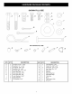
SHOWN jA FULL SIZE jB / / J ,jlV] jN I J NOT SHOWN FULL SIZE [_jQ _ KEY QTY. A B C D E F (3 H I J K 4 5 2 2 1 7 4 2 4 4 7 jR DESCRIPTION Hex Bolt, 5/16" x 1-3/4" Hex Bolt, 1/4" x 1-3/4" Hex Bolts, 3/8" x 3/4" Hex Bolt, 1/4" x 3/4" Carriage Bolt, 1/4" x 3/4" Hex Lock Nuts, 1/4" Hex Lock Nuts, 5/16" Hex Lock Nuts, 3/8" Lock Washers, 5/16" Nylon Washer Flat Washer, 5/16" KEY QTY.
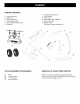
CARTON 1. 2. 3. 4. 5. 6. CONTENTS 7. Hitch Extension Bracket 8. Hitch Bracket 9. Hitch Tube 10. Flow Control Mount Bracket 11. Flow Control Arm 12. Hopper Cover Hardware Package (see page 4) Hopper Assembly Braces (2) Flow Control Rod Tube Support Strap Flow Control Mounting Tube Wheels (2) t_--3 .
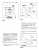
• Turnthespreaderupsidedownas showninfigure1. CROSSOVER TUBE SHAFT SUPPORT PLATE SHAFT SUPPORT PLATE CROSSOVER TUBE MIDDLE BOLT HITCH TUBE , , / / / / / _l'7 "MIDDLE / LOCK NUT 1/4" x 1-3/4" HEX BOLT 1/4" HEX LOCK NUT HITCH BRACE HITCH BRACE FIGURE 2 FIGURE 1 Tighten the nuts and bolts fastening the hitch braces to the hopper frame and the hitch tube, then tighten the middle lock nut fastening the hitch tube to the crossover tube. DO NOT COLLAPSE TUBES WHEN TIGHTENING.
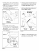
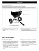
• • • Assemble a spacer, a 1-5/8" flat washer, a wheel (air valve facing out) and another 1-5/8" flat washer onto the end of the axle that has both the large and small holes. See figure 4. Install a 1/8" x 1-1/2" cotter pin into the small hole in the end of the axle. See figure 4. Open the bail on the drive pin and install it through the wheel and the large hole in the axle. Close the bail to lock the pin in place. See figure 4.
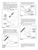
Assemble the vinyl grip onto the flow control arm. See figure 7. Insert the flow control arm down through the slot in the flow control bracket. Assemble the flow control • Hook the double bent end of the flow control rod through the hole in the slide gate bracket located near the bottom of the hopper. See figure 9. link (small hole) to the flow control arm using a 1/4" x 3/4" hex bolt, a nylon washer and a 1/4" hex lock nut as shown in figure 7. Tighten carefully.
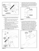
• Assemble the hitch bracket to the hitch extension • bracket using two 3/8" x 3/4" hex bolts (inserted from the bottom) and two 3/8" hex lock nuts. See figure 13. Assemble the hitch pin through the hitch bracket and the hitch extension bracket and secure with the hair cotter pin. See figure 13. NYLON WING NUT 5/16" FLAT WASHER HITCH PIN NYLON WASHER -J" 3/8" HEX LOCK NUT ADJUSTABLE STOP 1/4" x 3/4" CARRIAGE BOLT FIGURE 11 Position the flow control mounting bracket (figure 12). a.
KNOW YOUR SPREADER Read this owner's manual and safety rules before operating your spreader. Compare the illustration below with your spreader to familiarize yourself with the various controls and their locations. FLOW CONTROLARM ADJUSTABLE STOP / CLOSURE PLATE HITCH EXTENSION BRACKET J ' FLOW CONTROL ARM - Opens and closes the closure plate in the bottom of the hopper. ADJUSTABLE STOP - Limits how far the closure plate opens.
OPERATING TIPS • We do not recommend the use of any powdered lawn chemicals, due to difficulty in obtaining a satisfactory or consistent broadcast pattern. • Determine approximate square footage of area to be covered and estimate amount of material required. • Before filling the hopper make sure the flow control arm is in the off position and the closure plate is shut. • Break up any lumpy fertilizer as you fill the hopper. • Set the adjustable stop with the flow control arm still in the off position.
CUSTOMER RESPONSIBILITIES Read and follow the maintenance MAINTENANCE schedule and the maintenance procedures listed in this section. SCHEDULE Fill in dates as you complete regular service. Check for loose fasteners Check for worn or damaged parts Check tire inflation Service x x x x x Cleaning Lubricate Dates x x x CHECK FOR LOOSE FASTENERS CHECK FOR WORN OF DAMAGED PARTS LUBRICATE (See figure 16.) • Lightly apply automotive grease as needed to the sprocket and gear.
If the axle, slotted gear and sprocket assembly is disassembled, mark down the positions of the parts as they are removed. The drive wheel and sprocket positions in relation to the slotted gear determine which direction the spreader plate will spin. Be sure to reassemble them in their original positions. (Refer to figure 4 on page 5.) Use shim washers (Ref. no. 21 on pages 10 and 11 ) as needed for minimum backlash. Add grease to gear and sprocket. If the agitator hairpin becomes damaged can be replaced.
REPAIR PARTS FOR MODEL 486.24595 47 44 _58 39 11 66 54 9 54 11 39 41_, 60 _,_ _ F J_ _A_, 37 / 9 / / 6 _9 57 40 ® / / ! / 46 15 / / lj / 49 / / / / 35 // / 27 .... "3_S; 11 /- /' t 9 25 / 50 24 23 10 55 / 13_ 7 9 14 24 23 xX 21 \ .... ....... / 18 ® 17 / 021 22 43 37 16 \ \\ 50 56 50 37 14
REPAIR PARTS FOR MODEL REF. NO. PART NO. QTY. 1 2 44480 43882 1 4 Hopper Rivet, Stainless 35 36 3 4 5 6 62482 44462 23753 23758 1 1 Ass'y, Guide Closure Tube, Frame 37 39 1 1 Slide Gate Angle Bracket Slide Gate Bracket 40 41 7 8 9 10 11 43082 24857 43013 43808 43084 5 1 Nut, Hex Lock 3/8-16 Flow Control Link 42 43 17 1 Nut, Hex Lock 1/4-20 Thd.* Tube, Crossover 44 45 12 13 14 15 16 43086 43064 48864 48511 25080 6 6 6 1 2 Bolt, Hex 5/16-18 x 1-3/4" Lg.
.... For repair of major brand appliances in your own home ...................... no matter who made it, no matter who sold it! 1-800-4-MY-HOM EsMAnyt,me, dayorn,ght (1-800-469-4663) www.sears.co To bring in products such as vacuums, lawn equipment and electronics for repair, call for the location of your nearest Sears Parts & Repair Center. 1-800-488-1 222 Anytime, day or night www.sears.