
Manual

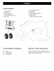
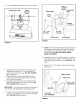
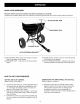

• Assemble a spacer, a 1-5/8" flat washer, a wheel (air
valve facing out) and another 1-5/8" flat washer onto
the end of the axle that has both the large and small
holes. See figure 4.
• Install a 1/8" x 1-1/2" cotter pin into the small hole in
the end of the axle. See figure 4.
• Open the bail on the drive pin and install it through
the wheel and the large hole in the axle. Close the
bail to lock the pin in place. See figure 4.
DRIVE PIN
118" x 1-1/2"
COTTER PIN
SPACER
1-5/8" DIA.
FLAT WASHER
FIGURE 4
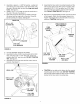
• Turn the spreader upright on its wheels.
• Assemble the flow control mounting tube to the hitch
tube using two 5/16" x 1-3/4" hex bolts, 5/16" lock
washers and 5/16" hex lock nuts. DO NOT TIGHTEN
YET. See figure 5.
• Assemble the vinyl cap onto the flow control mount-
ing tube. See figure 5.
VINYL CAP
5116" x 1-314"
HEX
5116" LOCK
_ WASHER
:_÷_"--. 5/16" HEX
LOCK NUT
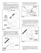
Assemble the flow control mounting bracket and the
tube support strap to the flow control mounting tube
using two 5/16" x 1-3/4" hex bolts, four 5/16" wash-
ers, two 5/16" lock washers and two 5/16" hex lock
nuts. DO NOT TIGHTEN YET. See figure 6.
Remove the preassembled bolt and nut from the front
of the hopper. Attach the tube support strap to the
hopper and hopper strap using the bolt and nut you
removed. TIGHTEN. See figure 6.
PREASSEMBLED
BOLT AND NUT
TUBE
SUPPORT" "....
STRAP
©
FIGURE 6
TIGHTEN the two bolts which fasten the flow control
mounting tube to the hitch tube. DO NOT TIGHTEN
the two bolts which fasten the flow control mounting
bracket to the flow control mounting tube.
FIGURE 5