
Manual

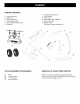
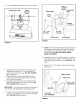

Assemble the vinyl grip onto the flow control arm.
See figure 7.
Insert the flow control arm down through the slot in
the flow control bracket. Assemble the flow control
link (small hole) to the flow control arm using a 1/4" x
3/4" hex bolt, a nylon washer and a 1/4" hex lock nut
as shown in figure 7. Tighten carefully. The flow
control link should be sung but should pivot with no
more than slight resistance.
1/4" HEX
LOCK NUT
\
NYLON......_
WASHER
1/4"x 3/4"
HEXBOLT
/
/
FIGURE 7
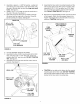
Assemble the flow control arm to the flow control
mounting bracket using a 1/4" x 3/4" hex bolt, two
nylon washers and a 1/4" hex lock nut. Tighten
carefully. The flow control arm should be snug but
should pivot with no more than slight resistance. See
figure 8.
1/4" HEX
LOCK NUT
1/4" x 314"
HEX BOLT
(2) NYLON
WASH ERS '_
\,
FIGURE 8
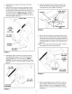
• Hook the double bent end of the flow control rod
through the hole in the slide gate bracket located
near the bottom of the hopper. See figure 9.
HOPPER
SLIDE GATE
BRACKET
FIGURE 9
FLOW CONTROL
ROD
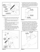
• Place a 5/16" flat washer onto the other end of the
flow control rod. Insert the end of the rod through the
curved slot in the flow control mounting bracket and
through the hole in the flow control link. Secure with a
5/16" flat washer and a 3/32" x 3/4" cotter pin. See
figure 10.
NOTE: You can leave off the second washer if there is
not enough room on the end of the rod.
5/16" FLAT
WASHER
FIGURE 10
3/32" HAIR
COTTER PIN
Place the adjustable stop into the "ON" end of the
slot in the top of the flow control mounting bracket.
Secure with the 1/4" x 3/4" carriage bolt, a nylon
washer, a 5/16" flat washer and the nylon wing nut.
See figure 11.