
Manual

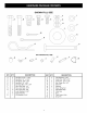
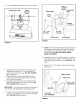

NYLON
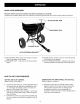
WING NUT
5/16" FLAT
WASHER
NYLON
WASHER
ADJUSTABLE
STOP
1/4" x 3/4"
CARRIAGE BOLT
FIGURE 11
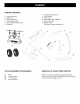
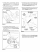
Position the flow control mounting bracket (figure 12).
a. Push on flow control arm until it locks in "OFF"
position.
b. Slide flow control mounting bracket along tube
until closure plate in bottom of hopper just
closes.
c. Snug the 1/4" lock nuts just enough to hold flow
control mounting bracket in place.
d. Set adjustable stop at "5". Pull flow control arm
against stop. Verify that closure plate has
opened about half way.
e. If closure plate does not open half way, adjust
position of flow control mounting bracket until
closure plate will open about half way at "5" and
will still close when arm is locked in "OFF"
position. Tighten 1/4" lock nuts.
FLOW
CONTROL
ARM
\
\
\
\
\
ADJUSTABLE
STOP
(SETTING "5")
FIGURE 12
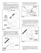
• Assemble the hitch bracket to the hitch extension
bracket using two 3/8" x 3/4" hex bolts (inserted from
the bottom) and two 3/8" hex lock nuts. See figure 13.
• Assemble the hitch pin through the hitch bracket and
the hitch extension bracket and secure with the hair
cotter pin. See figure 13.
HITCH PIN
-J" 3/8" HEX
LOCK NUT
FIGURE 13
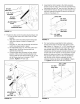
For most vehicles, assemble the hitch extension
bracket to the holes in the hitch tube shown at the
top of figure 14. Use two 1/4" x 1-3/4" hex bolts and
1/4" hex lock nuts tightened only finger tight. Attach
the spreader hitch to your vehicle hitch. Check for
interference with the spreader directly behind and out
to both sides of the vehicle. Lift the spreader at each
position to make sure there is no interference with
the spreader's flow control. If there is interference
with the rear of the vehicle, assemble the hitch
extension bracket as shown at the bottom of figure
14. Tighten the bolts and nuts when finished.
114" x 1-314"
HEX BOLT
1/4" HEX
LOCK NUT
! i
i
6).
FIGURE 14