Owner's Manual cnnFTSn#+ 16.5 HP ELECTRIC START 42" MOWER 6 SPEED TRANSAXLE LAWN TRACTOR Model No. 917.271110 • Safety • Assembly • Operation • Maintenance • Repair Parts CAUTION: Read and follow all Safety Rules and Instructions before operating this equipment. Sears, Roebuck and Co.
Warranty ................................................. 2 Safety Rules ........................................... 2 Assembly ................................................ 8 Operation .............................................. 12 Maintenance Schedule ......................... 19 Maintenance ......................................... 19 Product Specifications ........................... 5 Service and Adjustments ...................... 23 Storage .................................................
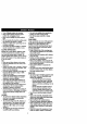
•Tum offblades whennotmowing. • Stop engine beforeremovinggrass catcheror uncloggingchute. • Mow only in daylightor goodartificial light. • Do not operatethe machinewhile under the influenceof alcoholor drugs. • Watchfor trafficwhen operatingnear or crossingroadways. • Use extra care when loadingor unloadingthe machineintoa trailer or truck. SLOPE OPERATION • Do nottryto stabilizethe machineby puttingyourfoot on the ground. • Do not use grasscatcheron steep slopes.
before restarting. • Never make adjustmentsor repairswith the engine running. • Grass catchercomponentsare subject to wear, damage,and deterioration, whichcouldexpose movingpartsor allowobjectsto be thrown.Frequently checkcomponentsand replacewith manufacturer'srecommendedparis, when necessary. Mowerbladesare sharpand can cut. Wrap the blade(s)or wear gloves,and use extracautionwhen servicing them. Check brakeoperationfrequently. Adjustand serviceas required.
PRODUCT SPECIFICATIONS GASOLINE CAPACITY AND TYPE: 1.25 GALLONS OIL TYPE (API-SF/SG/SH): SAE 30 (above 32°F) SAE 10W-30 (below 32°F) OIL CAPACITY: W/RLTER: 4.0 PINTS WK_FILTER:3.5 PINTS SPARK PLUG: GAP: .030") Champion J19LM STD361458- UNLEADED REGULAR GROUND SPEED FORWARD: (MPH): 1sr 1.1 2ND 1.4 3RD 2.3 4TM 3.5 5TM 4.5 6 TM REVERSE: 6.0 1.7 Shouldyou experienceany problemyou cannoteasilyremedy,please contactyour nearest SearsAuthorizedServiceCenter.
Parts Bag contentsshownfull size (1) Hex Bolt 5/16-18 x 1-1/4 © (1) Hex Bolt 3/8-16 x I (1) Lockwasher 3/8 Q (1) Large Rat Washer (1) Locknut 5/16-18 (1) Knol_ (1) Shoulder Bolt 5/16-18 (1) Washer 17/32 x 1-3/16 x 12 Gauge (2) Washers 3/16 x3/4 x 16 Gauge (2) Hex Bolts 114-20 x3/4 liltlliillllliillllillll (2) Screws #10 x 5/8 _. (2) Weld Nuts #10 _.
Parts packed separately in .carton Steering Boot Seat Video Cassette Plate Steering Wheel I Manual Parts Bag _(2) (2) Shoulder Bolts Centerlock Nuts (2) Washers 3/8 x 7/8 x 14 Gauge Parts Bag contentsnot shownfull size (2) Front LinkAssemblies /_ _St_ri_g Insert in Steering Wheel Adapter _)..
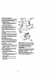
Yournewtractorhasbeen assembledat the factorywith exceptionof thoseparts left unassembledfor shippingpurposes.To ensuresafe and properoperationof yourtractor all partsand hardwareyou assemblemustbe tightenedsecurely.Use the correcttools as necessaryto insurepropertightness.Review the videocassettebeforeyou begin. TOOLS REQUIRED FOR are horizontal(leftto dght)and slide ASSEMBLY insidebootand ontoadapter.
HOW TO SET UP YOUR TRACTOR CONNECT BATTERY ACAUTION: Do not short battery terminals by allowing a wrench or any other object to contact both terminals at the same time. Before connecting battery, remove metal bracelets, wristwatch bands, rings, etc. Positive terminal must be connected first to prevent sparking from acciclental grounding. • Remove cardboard packing from seat pan and lift seat pan to raised position. • Open battery box door and remove protective plastic.
CHECK TIREPRESSURE Weld NutFrom Thetiresonyourtractor wereovednflated The Top atthefactory forshipping purposes. Lock Correct tirepressure isimportant forbest Weld Washer cutting performance. Nut • Reduce tirepressure toPSIshown in "PRODUCT SPECIFICATIONS" on page 5 of this manual. CHECK DECK LEVELNESS For best cutting results, mower housing should be properly leveled. See "TO LEVEL MOWER HOUSING" in the Service and Adjustments section of this manual.
ASSEMBLE GAUGE WHEELS TO MOWER DECK The gauge wheels are designed to keep the mower deck in proper position when operating mower. Be sure they are properly adjusted to ensure optimum mower performance. • Assemble gauge wheels with tractor on a flat level surface. • - Adjust mower to desired cutting height (See "TO ADJUST MOWER CUTTING HEIGHT" in the Operation section of this manual). • With mower in desired height of cut position, gauge wheels should be assembled so they are slightly off the ground.
These symbolsmay appearon yourtractoror in literaturesuppliedwith the product. Learn and understandtheirmeaning.
KNOWYOURTRACTOR READ THISOWNER'S MANUAL ANDSAFETY RULES BEFORE OPERATING YOUR TRACTOR Compare theillustrations withyourtractor tofamiliarize yourself withthelocations of various controls andadjustments. Savethismanual forfuturereference.
The operationof any tractorcan resultin foreignobjectsthrownintothe I eyes,whichcan resultin severeeye damage.Alwayswear safetyglasses or eye shieldswhileoperatingyourtractoror performingany adjustmentsor repairs.We recommenda wide visionsafety mask over the spectacles,or standardsafety glasses. I HOW TO USE YOUR TRACTOR Yourtractoris equippedwith an operator presencesensingswitch.When engine is running,anyattemptby the operatorto leavethe seat withoutfirstsettingthe parkingbrakewillshut offthe engine.
• The average lawnshouldbe cutto approximately2-1/2 inchesduringthe coolseasonand to over 3 inchesduring hot months. For healthierand better lookinglawns,mowoften and after moderategrowth. • For bestcuttingperformance,grass over 6 inchesin heightshouldbe mowedtwice. Make the firstcut relativelyhigh;the secondto desired height. TO OPERATE MOWER Yourtractoris equippedwith an operator presencesensingswitch.
mixoilwithgasoline. Purchase fuelin WARM WEATHER STARTING (50° F quantities thatcanbeusedwithin30 AND ABOVE) daystoassure fuelfreshness. • When engine starts,move the throttle IMPORTANT: Whenoperating intempera- controlto the fast position. turesbelow 32°F(0°C), use fresh, clean • The attachmentsand grounddrivecan wintergradegasolineto help insuregood ,_dAweatherstarting.
• When mowing large areas, start by turning to the right so that clippings will discharge away from shrubs, fences, driveways, etc. After one or two rounds, mow in the opposite direction making left hand tums until finished. • If grass is extremely tall, it should be mowed twice to reduce load and possible fire hazard trom dried clippings. Make first cut relatively high; the second to the desired height. • Do not mow grass when it is wet. Wet grass will plug mower and leave undesirable clumps.
CUSTOMER RESPONSIBILITIES MAINTENANCE AS YOU SCHEDULE _./_ __..,,,__.,,_€.J COMPLETE DATES lie Check Brake Check T R Operation t_ Tire Pressure I_ i Check Operator Presence : Intedock Systems and V ° CheckforLooseFa_enera SharperdIReplace V p Mower V* I,/, Blades T LuStre.
TRACTOR Alwaysobservesafety ruleswhen performingany maintenance. BRAKE OPERATION If tractor requires more than six (6) feet stopping distance at high speed in highest gear, then brake must be adjusted. (See "TO ADJUST BRAKE" in the Service and Adjustments sectionof this manual). TIRES • Maintain proper air pressure in all tires (See "PRODUCT SPECIFICATIONS" on page 5 of this manual). • Keep tires free of gasoline, oil, or insect control chemicals which can harm rubber.
• Coat terminals with grease or petroleum jelly. • Reinstall battery (See =CONNECT BATTERY" in the Assembly section of this manual). V-BELTS Check V-belts for deterioration and wear after 100 hours of operation and replace if necessary. The belt3 are not adjustable. Replace belts if they begin to slip from wear. TRANSAXLE COOLING Keep transaxle free from build-up of dirt and chaff which can restrict cooling.
TOSERVICE CARTRIDGE IN-LINE • Replace a dirty, bent, or damaged cartridge. NOTE: Do not wash the paper cartridge or use pressurized air, as this will damage the cartddge. • Reinstall the pre-cleaner (cleaned and oiled) over the paper cartridge. • Reassemble air cleaner, wing nut, cover and tighten knob securely. CLEAN AIR INTAKFJCOOLING AREAS To insure proper cooling, make sure the grass screen, cooling fins, and other external surfaces of the engine are kept clean at all times.
,_CAUTION: Before pedorming any service or adjustments: • Depress clutch/brake pedal fully and set parking brake. • Place motion control lever in neutral (N) position. • Place attachment clutch in "DISENGAGED" position. • Turn ignition key "OFF" and remove key. * Make sure the blades and all moving pads have completely stopped. • Disconnect spark plug wire from spark plug and place wire where it cannot come in contact with plug. TO REMOVE MOWER Mowerwillbe easier to removefrom the rightside oftractor.
TO LEVEL MOWER HOUSING Adjustthe mowerwhiletractoris parked on levelgroundor driveway. Make sure tiresare properlyinflated(See =PRODUCT SPECIFICATIONS'). If tires are over or underinflated,you willnot propedy adjustyourmower. SIDE-TO-SiDE ADJUSTMENT • Raise mowerto itshighestposition. ° At the midpointof bothsides of mower, measureheightfrom bottomedge of mowerto ground. Distance=A"on both sidesof mower shouldbe the same or within1/4" of each other.
BELT INSTALLATION - and inside all belt guides. • Install mower in reverse order of removal instructions. • Install new belt in reverse order of removal. • Make sure belt is in all pulley grooves Idler Pulley IdlerPulley Mandrel Mandrel Pulley TO ADJUST BRAKE Your tractor is equippe_ with an adjustable brake system which is mounted on the right side of the transaxle. If tractor requires more than six (6) feet stopping distance at high speed in highest gear, then brake must be adjusted.
TOREMOVE WHEEL FORREPAIRS • Block up axle securely. • Remove axle cover, retaining ring and washers to allow wheel removal (rear wheel contains a square key - Do not lose). • Repair tire and reassemble. • On rear wheels only: align grooves in rear wheel hub and axle. Insert square key. • Replace washers and snap retaining ring securely in axle groove. • Replace axle cover. NOTE: To seal tire punctures and prevent flat tires due to slow leaks, tire sealant may be purchased from your local parts dealer.
TOREPLACE FUSE Replace with30ampautomotive-type plug-in fuse.Thefuseholder islocated behind thedash. ENGINE TO ADJUST THROI"FLE CONTROL CABLE The throttle control has been preset at the factory and adjustment should not be necessary. Check adjustment as described below before loosening cable. If adjustment is necessary, proceed as follows: • With engine not running, move throttle control lever from slow to choke position. Slowly move lever from choke to fast position.
Immediatelyprepareyourtractorfor storage at the end ofthe seasonor ifthe tractor willnot be used for 30 daysor more. _CAUTION: Never store thetractorwith gasolinein the tank insidea building where fumesmay reach an openflame or spark. Allowthe engineto coolbefore storingin any enclosure. TRACTOR Remove mowerfrom tractorfor winter storage.Thiswill allowyouto clean itthoroughly.Removeall dirt,grease, leaves, etc. Store in a clean, dry area.
TROUBLESHOOTING CHART PROBLEM Will not start CAUSE CORRECTION • Out of fuel. • Engine not'CHOKED" prop e_. • Engine flooded. • Bad spark plug. • Dirty air filter. • Dirty fuel filter. • Water in fuel. • Loose or damaged wiring. • Carburetor out of adjustment. • Hard to start • Dirty air filter. • Bad spark plug. • Weak or dead battery. • Dirty fuelfilter. • Stale or dirty fuel. • Loose or damaged wiring. • Carburetor out of adjustment. • Engine wi, not turn over Engine valves out of adjustment.
TROUBLESHOOTING CHART CAUSE PROBLEM Lose ofpower (cont'd)• Build-up CORRECTION of grass, leaves and trash under mower. • Dirty fuel filter. • Stale or dirty fuel. ing. • Clean/replace air filter. • Check oil level/change oil. • Clean and regap or change spark plug. • Replace fuel filter. • Drain fuel tank and refill with • Water in fuel. fresh gasoline. • Drain fuel tank and carburetor, • Dirty air filter. • Low oil level/dirty oil. • Faulty spark plug. • Spark plug wire loose.
TROUBLESHOOTING CHART PROBLEM CAUSE CORRECTION Poor grass discharge (cont'd) • Mower deck not level. • Low/uneven tire air pressure. • Level mower deck, • Check tires for proper air pressure. • Worn, bent or loose blade. • • Buildup of grass, leaves and trash under mower. • Mower drive belt worn. • Replace/sharpen blade. "i3ghten blade boll Clean underside of mower hous- Headlight(s)not working(if so equipped) Batterywillnot charge • Blades impropedy installed. Replace mower drive bait.
TRACTOR - - MODEL NUMBER 917.270720 SCHEMATIC m_p [ BAI-rERY SOLENOID FUSE 30 AMP. AMMETER (OPTIONAL) I __ IGNITION SWITCH _-_:-_-,-] I i i P ATT'MENTCLUTCH (CLUTCHOFF) • :l-: D o: =TAD'n_" _ a • ...... ,,PED_. UP) I :---_---_ ! ' t I I fI :J -,,,___'. ",_' LINE D €,_ , I---_ r, ! A (NOTOCCUPIED) / I ,- ....... , i F'U_:L-_J¥-_-F SOLENOID • .>'_,_;;;o_-' • PRESENCE RELAY#1 A IGNITION u.
TRACTOR - - MODEL NUMBER 917.271110 ELECTRICAL \ i i / i i / i s i 32
TRACTOR - - MODEL NUMBER 917.271110 ELECTRICAL KEY NO. 1 2 3 4 6 8 16 19 20 21 22 24 25 26 28 29 30 31 32 33 40 41 PART NO. DESCRIPTION 163465 74760412 STD551025 STD551125 STD541025 156417 161343 STD551125 733504(X) 147430 4152J 4799J 146147 108824X 4207J 160784 140301 124211X 141226 109310X 161351 71110408 Battery,12 Volt 28 Amp Bolt, Hex 114-20 x 3/4 Washer 9/32 x 5/8 x 16 Gauge Washer, Lock 1/4 Nut, Hex 114-20 Case, Battery Mech Hinge Switch, Interlock N. OPNJN.
TRACTOR - - MODEL NUMBER 917.271110 CHASSIS AND ENCLOSURES I 28 58 12 53 \ _1 52 54 _13 3 60 25 34 55
TRACTOR -- MODEL NUMBER 917.271110 CHASSIS AND ENCLOSURES KEY PART NO. NO. 1 160392 DESCRIPTION ChassisAssemUy 2 3 4 5 9 10 11 12 13 14 17 18 140356 17490612 19131216 155272 161917X013 STD533710 155927 145660 155936 17490608 144983X558 126938X Drawbar Screw, Thd.,Roll. 3/8-16x3/4 Washer 13/32 x 3/4 x 16 Gauge Bumper Hood/Dash Dash Bolt, Carriage 3/8-16x3/4 Panel, Dash, LH Clip]',merman Gd]le P4. Panel, Dash, RH Screw, Thd.,Roll.
TRACTOR - - MODEL NUMBER 917.
TRACTOR -- MODEL NUMBER 917.271110 GROUND DRIVE KEY NO. 1 PART NO. 161451 KEY NO. DESCRIPTION PART NO. Transaxle(See Breakdown) Dana, Model Number4360-122 Spdng, Return, Brake Pulley, Transaxle Ring, Retainer Strap, Torque Screw, Thd.,Rolt.
TRACTOR " " MODEL NUMBER 917.271110 STEERING ASSEMBLY ,'L':..... _...... i i¸----- , I _. $2 44...
TRACTOR - - MODEL NUMBER 917.271110 STEERING ASSEMBLY KEY PART NO. NO.
TRACTOR - - MODEL NUMBER 917.
TRACTOR -- MODEL NUMBER 917.271110 ENGINE KEY NO. PART NO. 1 2 3 162156 17720410 4 DESCRIPTION 159420 Control, Throt I Ch Screw, Hex Thd Cut 1/4-20x5/8 T Engine (See Breakdown) Kohler Model No. CV16-43513 Muffler 14 15 16 23 29 31 13280328 13200300 STD551231 159880 137180 109202X Nipple, Pipe 3/8 NPT x 3-1/2 Elbow, Std 90 Degree 3/8-18 Npt Washer Shield, BRN/DBR Guard Arrestor, Spark Tank, Fuel 32 33 35 37 38 40 44 158990 123487X 17490512 137040 .......
TRACTOR -- MODEL NUMBER 917.271110 SEAT ASSEMBLY 5 21 1 2 3 4 5 6 7 8 9 10 11 PART NO. .... DESCRIPTION KEY NO. PART NO.
TRACTOR - - MODEL NUMBER 917.271110 DECALS 6 4 3 10 / KEY NO. 1 3 4 5 PART NO. KEY NO. DESCRIPTION 156368 163200 163202 163207 Decal, Oper. Instr. Decal, Hood, R.H. Decal, Hood, L.H. Decal, Fender Sd White Rad/6sp 42" Decal, Customer Maintenance Decal, Dash Pnl Kohler 16.
TRACTOR - - MODEL NUMBER 917.271110 LIFT ASSEMBLY 28 27 25 24 23 .I / ,/ /' ,/ 49 1' / / 30 3 \ 13 26 5 4 13 13 20 19 15 13 32 f 44
TRACTOR - - MODEL NUMBER 917.271110 UFT ASSEMBLY KEY NO. .... PART NO. DESCRIPTION 1 2 3 4 5 6 7 8 11 12 13 15 16 17 159460 159471 105767X 120(X)062 19211621 120183X 125631X 122365X 139865 139866 STD624008 127218 73350800 130171 Wire Asm Inner/Sprg w/Plunger LT Shaft Asm. Lift Pin Groove E Ring #5133-62 Washer 21/32xl x21Ga.
TRACTOR - - MODEL NUMBER 917.271110 MOWER DECK 58 17 ,_-21 21 22 '23 24 _2 26 16 \ 28 \ 27 13_ 18 _11 46
TRACTOR - - MODEL NUMBER 917.271110 MOWER DECK KEY NO. PART NO. 1 2 3 144393 STD533107 138017 4 5 6 8 138440 STD624008 130832 850857 KEY NO. PART NO. DESCRIPTION 55 56 56 59 67 68 155046 122052X 140086 141043 162113 144200 Arm, Idler Spacer, Retainer Spring, Torsion Brakes Guard, TUV Idler Knob Custom Oval V-Belt Retainer Spdng Arm, Suspension, Rear Bolt, Hex 3/8-24 x 1.
TRACTOR - - MODEL NUMBER 917.
TRACTOR - - MODEL NUMBER 917.271110 DANA TRANSAXLE-- MODEL NUMBER D4360-122 KEYPART NO.NO. KEYPART NO.NO. DESCRIPTION 1 2 3 4 5 160955 2274J 134400 105904X 160940 Housing, Upper Screw, Tapping, 1/4-20 X .734 Ball, Detent Spdr_, Detent Screw, Tapping, No. 10-24 X .
TRACTOR - - MODEL NUMBER 917.
TRACTOR - - MODEL NUMBER 917.271110 KOHLER ENGINE - MODEL NUMBER CV16, TYPE NUMBER PS-43513 CYLINDER H EADNALVE/BREATHER KEYPART NO.NO. 1 2 3 4 5 6 7 8 9 10 11 12 13 14 15 16 17 18 19 2O 21 22 23 24 12-351-02 12-755-63 12-411-01 12-041-10 12-017-01 12-017-02 12-016-01 12-016-02 X-75-23 12-318-19 25-186-01 12-599--03 M-0640034 12-089-01 12-173-01 12-755-03 12-468-05 12-112-13 12-086-15 X-425-9 12-326-03 M-0645020 12-096-07 M-0545010 12-018-01 12-402-02 CRANKCASE KEYPART NO.NO.
TRACTOR - - MODEL NUMBER 917.271110 KOHLER ENGINE - MODEL NUMBER CV16, TYPE NUMBER PS-43513 IGNITION / ELECTRICAL I BLOWER HOUSING AND BAFFLES I 4 _, 13 _ I-- 11 10 12 20_.
TRACTOR - - MODEL NUMBER 917.271110 KOHLER ENGINE - MODEL NUMBER CV16, TYPE NUMBER PS-43513 IGNITION/ELECTRICAL KEYPART NO.NO. 1 2 3 4 12-086-14 12-468-03 24-162-03 M-0639016 5 6 7 8 9 10 11 12 13 14 15 16 17 12-112-01 12-157-03 41-403-09 X-22-11 236602 X-42-15 12-025-35 41-155-02 M-0548025 12-085-01 12-132-02 X-728-1 M-0545010 18 19 20 12-584-07 12-452-02 12-086-35 BLOWER HOUSING & BAFFLES KEYPART NO.NO. DESCRIPTION Screw, hex. flange MIOx1.Sx46 Washer, plain 3/8 Screen, grass Screw, hex.
TRACTOR - - MODEL NUMBER 917.
TRACTOR - - MODEL NUMBER 917.271110 KOHLER ENGINE- MODEL NUMBER CV16, TYPE NUMBER PS-43513 STARTING ENGINE CONTROLS SYSTEM KEYPART NO. NO. M-0839070 DESCRIPTION KEYPART NO.NO. Screw, hex. flange M8x1.25x70 (2) 2 3 4 5 6 7 8 25-O98-O5 12-755-54 12-227 -06 12-170-05 12-221-01 12-227-13 12-211-01 Starter assembly (Includes 3-8) Kit, drive end Cap, drive end Armature Kit,brush &spr_j Cap, commutator end Bolt, hex.
TRACTOR - - MODEL NUMBER 917.271110 KOHLER ENGINE - MODEL NUMBER CV16, TYPE NUMBER PS-43513 KEY NO. PART NO. DESCRIPTION C_N_HA_ J KEY NO. EXHAUST PART NO.
TRACTOR - - MODEL NUMBER 917.271110 KOHLER ENGINE - MODEL NUMBER CV16, TYPE NUMBER PS-43513 KEY NO. PART NO. KEY NO. DESCRIPTION 1 3 4 5 M-0641060 X-22-11 M-0629116 12-853-83 6 7 12-041-02 12-053-83 8 9 11 12 13 15 12-041-01 12-265-04 X-309-14 52-353-22 25-050-02 12-559-01 24 12-431-01 NOT ILLUSTRATED 12-757-02 12-757-03 12-041-O1 12-041-02 12-041-05 12`041-06 12-032-06 12-757-09 12-041-06 DESCRIPTION CRANKSHAFT FUEL SYSTEM KEYPART NO.NO. PART NO. KEYPART NO.NO. DESCRIPTION Nut, hex.
SUGGESTED GUIDE FOR SIGHTING SLOPES FOR SAFE OPERATION ONLY RIDE UP AND DOWN HILL, NOT ACROSS HILL O1 t.O SIGHT AND HOLD THIS LEVEL WITH SKY LINE OR TREE. 15 ° MAX. 1 greater than 15 ), never across the face. Make turns greduOperate your Tractor up and down the face of slopes (not ally to prevent tipping or loss of control. Exercise extreme caution when changing direction on slopes.
For the repairor replacementpartsyou need delivereddirectlyto yourhome Call7 am - 7 pm, 7 days a week 1-800-366-PART (1-800-366-7278) Para ordenar piezas con entrega a domicilio - 1-800-659-7084 For in--housemajorbrand repairservice Call 24 hoursa day, 7 daysa week 1-800-4-REPAIR (1-800-473-7274) Para pedir servicio de reparaci6n a domicilio - 1-800-676-5811 Forthe locationof a Sears Partsand RepairCenter in yourarea Call 24 hoursa day, 7 days a week 1-800-488-1222 it Illlll illllill II l For inform