User’s Guide for the C R AT E P R O A U D I O CSM8/12/16/24 Console Mixer In order to achieve maximum performance from your new Crate Pro Audio Mixer we recommend that you read this user’s guide prior to its use.
CSM8/12/16/24 Console Mixer Congratulations. You have selected one of the finest pieces of audio reproduction equipment available for use on stage, in the home studio, or for “institutional” use: a Crate Pro Audio Stereo Console Mixer. In order to derive the most benefit from the mixer, and to fully understand and appreciate its flexibility and versatility, please familiarize yourself with the mixer by reading through this User’s Guide prior to its use. And Thank You, from Table of Contents: Introduction .
CSM8/12/16/24 Console Mixer Introduction: In the world of professional sound reinforcement and audio reproduction there is no room for compromise. It is absolutely vital that the emotions of a performance are projected to your audience, not just sounds. Your new Crate Pro Audio CSM8/12/16/24 Console Mixer is a powerful tool which allows you to successfully bridge the gap between performers and audience without losing any of the “life” of the performance in the process.
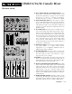
CSM8/12/16/24 Console Mixer The Input Channels: 1. LOW Z INPUT: The signal output from a low impedance microphone or a low impedance line level signal (such as a line out signal from an instrument amplifier) may be connected here by means of a shielded cable terminated with a male XLR plug. Pin 2 = “+,” pin 3 = “–,” and pin 1 = shield. 2. HIGH Z INPUT: The signal output from a high impedance microphone or a line level signal (such as an instrument, rhythm machine, tape deck, etc.
CSM8/12/16/24 Console Mixer The Master Section: 16 15 17 18 19 21 18. PFL OUTPUT JACK: Use this jack to send the channel’s PFL signal outputs to a studio monitor power amp/speaker or to a headphone distribution box for additional monitoring capabilities. 23 24 25 27 26 28 31 19. AUX RETURN JACKS: Use these jacks to return the processed signal from an external effect into the master mix. These jacks are stereo 1/4” connectors – ring = right, tip = left, sleeve = shield. 20.
CSM8/12/16/24 Console Mixer The Master Section (continued): 16 15 17 18 19 23: PHANTOM POWER: This switch, when depressed, applies 48 volts DC to pins 2 and 3 of the each channel’s low Z input jacks (#1, page 4) to accommodate microphones which require a source of phantom power for proper operation. (Mics not requiring phantom power are not affected by the presence of the DC voltage.) 24.
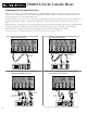
CSM8/12/16/24 Console Mixer Equalization Diagrams: Each input channel of the CSM8/12/16/24 has three bands of equalization which let you alter the tonal characteristics of the input signal. The EQs may be used to add “color” or to compensate for inadequacies of the original signal. They also may be used to cut frequencies to help eliminate unnatural sounds or to de-emphasize over-pronounced tones, and to help prevent acoustic feedback. Each EQ has a range of 30dB (+/-15dB).
CSM8/12/16/24 Console Mixer Connecting External Signal Processors: There are several ways to use external signal processors with the CSM8/12/16/24. Each of the mixer’s input channels has its own Insert jack, allowing a processor to be used on that particular channel. Figures 1 and 2 below show two ways of connecting a signal processor to the channel Insert jacks.
CSM8/12/16/24 Console Mixer Applications: Basic Mono Operation: This setup shows one way of using the mixer and one stereo power amplifier to run both the house speakers and the stage monitors. Two mono power amplifiers may be used in place of the one stereo amplifier. Connect the components as follows: (A) Connect a balanced or unbalanced signal cable between the mixer’s Mix Balanced Output and the power amplifier’s Channel 1 Input.
CSM8/12/16/24 Console Mixer Applications: Basic Stereo Operation: This setup shows one way of using the mixer and two stereo power amplifiers to run the system. By using both Aux 1 and 2 for monitor sends, a separate monitor mix can be had for each of two sets of monitor speakers. Connect the components as follows: (A) Connect a balanced or unbalanced signal cable between the mixer’s Left Balanced Output and the house power amplifier’s Channel 1 Input.
CSM8/12/16/24 Console Mixer Applications: DJ Setup: This setup shows one way of using the mixer and one stereo power amplifier to run the house speakers for a mobile DJ setup. Two mono power amplifiers may be used in place of the one stereo amplifier. Connect the components as follows: (A) Connect a balanced or unbalanced signal cable between the mixer’s Left Balanced Output and the house power amplifier’s Channel 1 Input. Connect the Right Balanced Output and the Channel 2 input in the same manner.
CSM8/12/16/24 Console Mixer Applications: House of Worship Installation: This setup shows one way of using the mixer and one stereo power amplifier to run both the house speakers and the stage monitors. Two mono power amplifiers may be used in place of the one stereo amplifier. Connect the components as follows: (A) Connect a balanced or unbalanced signal cable between the mixer’s Left Balanced Output and the house power amplifier’s Channel 1 Input.
CSM8/12/16/24 Console Mixer Applications: Separating Vocals and Instruments: This setup shows one way of using the mixer, one stereo and one mono power amplifier to run the system. Two sets of house speakers are required in this application: one for the vocals, the other for the instruments. Connect the components as follows: (A) Connect a balanced or unbalanced signal cable between the mixer’s Left Balanced Output and the house power amplifier’s Channel 1 Input.
CSM8/12/16/24 Console Mixer LEFT RIGHT AUX 1 AUX 2 AUX 3 AUX 4 PFL MIX System Block Diagram: LA LEFT TAPE OUT LA RIGHT TAPE OUT SUM PHANTOM POWER ON +48V LA PFL LEFT OFF SUM AUX 1 LOW Z AUX 2 PEAK/ SIGNAL T LA PFL RIGHT LA PFL MIX INSERT R T EQ BA CHANNEL FADER R T MIX FADER MUTE PFL LA SUM R PFL OUT R HEAD PHONES OUT T LA LA BA R PAN T HEADPHONES LEVEL BA AUX 3 RETURN AUX 4 RETURN BA R PAN T SUM BA AUX 3 RETURN 14 SUM LEFT TAPE IN BA RIGHT TAPE IN BA MIX
CSM8/12/16/24 Console Mixer Gain Level Diagram: MIC EQ FADER GAIN LINE MASTER FADER PAN INSERT +30 +20 +21dB MAX LINE +26dB +10 MAX MIC +13dB +21dB MAX.
CSM8/12/16/24 Console Mixer Technical Specifications SYSTEM INPUTS CSM8 CSM12 CSM16 CSM24 All models TAPE INS / TAPE OUTS RCA jacks 47k ohm input impedance +4dBv (1.23V RMS) @ High-Z nominal output Max. Sensitivity -10dBv (.245V RMS) Max. Input Accepted +30dBv (24.