Crestron FT-600 FlipTop™ Basic Operations & Installation Guide
Regulatory Compliance This product is Listed to applicable UL Standards and requirements by Underwriters Laboratories Inc. As of the date of manufacture, the FT-600 has been tested and found to comply with specifications for CE marking. Federal Communications Commission (FCC) Compliance Statement This device complies with part 15 of the FCC Rules.
Crestron FT-600 FlipTop Basic Contents FlipTop Basic: FT-600 1 Introduction ............................................................................................................................... 1 Features and Functions ................................................................................................ 1 Specifications .............................................................................................................. 3 Physical Description ...............................
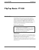
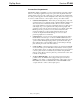
Crestron FT-600 FlipTop Basic FlipTop Basic: FT-600 Introduction The FT-600 FlipTop™ Basic by Crestron® provides a highly configurable connectivity solution in a stylish, flush mount tabletop design. Flipping open the “FlipTop” lid accesses its connection compartment where interface cables and connectors are kept at the ready for plugging in laptop computers, mobile devices, AV source, and other equipment.
FlipTop Basic Crestron FT-600 Connection Compartment The FT-600 is highly configurable to provide a well-organized connectivity solution tailored to each unique application. It provides options for both pullout cables and panel-mounted connectors, with or without ac power outlets. It comes standard with two cable pass-through plates and four blank plates, all of which can be swapped out for a choice of cable retractors, connector plates, and ac power outlet modules.
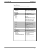
Crestron FT-600 FlipTop Basic Specifications Specifications for the FT-600 are listed in the following table.
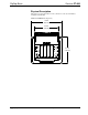
FlipTop Basic Crestron FT-600 Physical Description This section provides information on the connections, controls, and indicators available on the FT-600. FT-600 Overall Dimensions (Top View) 7.98 in (203 mm) 6.22 in (158 mm) 6.77 in (172 mm) 4 • FlipTop Basic: FT-600 Operations & Installation Guide – DOC.
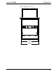
Crestron FT-600 FlipTop Basic FT-600 Overall Dimensions (Front View) 6.88 in (175 mm) 7.28 in (185 mm) Operations & Installation Guide – DOC.
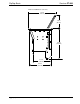
FlipTop Basic Crestron FT-600 FT-600 Overall Dimensions (Side View) 7.88 in (200 mm) 3.75 in (95 mm) 8.59 in (218 mm) 5.12 in (130 mm) 6.07 in (155 mm) 6 • FlipTop Basic: FT-600 Operations & Installation Guide – DOC.
Crestron FT-600 FlipTop Basic FT-600 (Oblique View) Operations & Installation Guide – DOC.
FlipTop Basic Crestron FT-600 FT-TS600 (Bottom View) 1 Connectors, Controls, and Indicators 8 • FlipTop Basic: FT-600 1 # CONNECTORS , CONTROLS, AND INDICATORS 1 G (Ground) DESCRIPTION (1) 6-32 screw, chassis ground lug Operations & Installation Guide – DOC.
Crestron FT-600 FlipTop Basic Setup Supplied Hardware The hardware supplied with the FT-600 is listed in the following table. Supplied Hardware for the FT-600 DESCRIPTION PART NUMBER QUANTITY Metal, Plate, Mounting 2036985 2 Screw, 10-32 x 2”, Steel, Socket HD, Zinc 2037109 4 Small Hole Plug 2036647 4 Large Hole Plug 2036649 4 Small Bushing, 5/16” ID, 0.5” OD 2009522 4 Large Bushing, 0.55” ID, 0.
FlipTop Basic Crestron FT-600 Cable Management Plate Installation Mounting Plate Dovetail Inserts Here Bushing Cable Management Plates (2) 06-32 x 1/4” Screws (2) Mounting in a Surface The FT-600 is designed to mount in a horizontal surface, such as a desktop, lectern, or podium. The following diagram illustrates the required opening size to accommodate the FT-600. A cutout template (40143) is included.
Crestron FT-600 FlipTop Basic Use the following procedure to mount the FT-600. 1. Position the FT-600 in the mounting hole. Mounting Plate Stud Locations Studs for Mounting Plate Surface Cutout 2. Install the four #10-32 socket screws (2037109) in the metal mounting plates (2036985) (two screws per plate). Refer to the following illustration. Operations & Installation Guide – DOC.
FlipTop Basic Crestron FT-600 Mounting Plate Installation Mounting Surface Mounting Plates (2) (2036985) Screws (4) #10-32 x 2” (2037109) 3. Slide the mounting plates over the studs on each side of the FT-600. 4. Turn the four #10-32 socket screws equally, until they contact the underside of the mounting surface. NOTE: Do not overtighten the #10 screws as this may damage the surface or the unit. 12 • FlipTop Basic: FT-600 Operations & Installation Guide – DOC.
Crestron FT-600 FlipTop Basic Resources Further Inquiries To locate specific information or resolve questions after reviewing this guide, contact Crestron's True Blue Support at 1-888-CRESTRON [1-888-273-7876] or, for assistance within a particular geographic region, refer to the listing of Crestron worldwide offices at www.crestron.com/offices. To post a question about Crestron products, log onto Crestron’s Online Help at www.crestron.com/onlinehelp.
FlipTop Basic Crestron FT-600 This page is intentionally left blank. 14 • FlipTop Basic: FT-600 Operations & Installation Guide – DOC.
Crestron FT-600 FlipTop Basic This page is intentionally left blank. Operations & Installation Guide – DOC.
Crestron Electronics, Inc. 15 Volvo Drive Rockleigh, NJ 07647 Tel: 888.CRESTRON Fax: 201.767.7576 www.crestron.com Operations & Installation Guide – DOC. 7596C (2038123) 10.14 Specifications subject to change without notice.