Crestron IM-RXV1-M & IM-RXV3-M iMedia Receiver with Video and Mic Input Operations & Installation Guide
This document was prepared and written by the Technical Documentation department at: Crestron Electronics, Inc. 15 Volvo Drive Rockleigh, NJ 07647 1-888-CRESTRON All brand names, product names and trademarks are the property of their respective owners. ©2007 Crestron Electronics, Inc.
Crestron IM-RXV1-M & IM-RXV3-M iMedia Receiver with Video & Mic Input Contents iMedia Receiver with Video and Mic Input: IM-RXV1-M & IM-RXV3-M 1 Introduction ............................................................................................................................... 1 Features and Functions ................................................................................................ 1 Applications......................................................................................
Crestron IM-RXV1-M & IM-RXV3-M iMedia Receiver with Video & Mic Input iMedia Receiver with Video and Mic Input: IM-RXV1-M & IM-RXV3-M Introduction Crestron's iMedia (IM) provides an extremely simple and affordable multimedia presentation control solution for small conference rooms and training rooms. No comparable solution comes close to matching iMedia's speed and ease of installation, intuitive operation, and incredibly low cost.
iMedia Receiver with Video & Mic Input Crestron IM-RXV1-M & IM-RXV3-M The iMedia Transport The iMedia transport utilizes a single CAT5e* type cable to transmit computer RGB, video, and stereo audio signals to a single display device. A typical XGA signal (1024 X 768 pixels at 60 Hz) can be transmitted up to 84 feet using iMedia, while higher resolutions up to 1600 x 1200 can be handled over shorter distances. Composite video signals can be transmitted up to 218 feet.
Crestron IM-RXV1-M & IM-RXV3-M iMedia Receiver with Video & Mic Input Applications The IM-RXV1-M and IM-RXV3-M are part of the Crestron® iMedia line of network devices, room control systems and signal routing solutions. The line of iMedia devices includes receivers and transmitters. Consult the Crestron website (http://www.crestron.com/) for a complete and current listing of the iMedia product line.
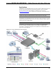
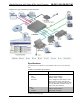
iMedia Receiver with Video & Mic Input Crestron IM-RXV1-M & IM-RXV3-M IM-RXV3-M in a Typical Installation for Media Presentation Specifications Specifications for the IM-RXV1-M and IM-RXV3-M are listed in the following table.
Crestron IM-RXV1-M & IM-RXV3-M iMedia Receiver with Video & Mic Input IM-RXV1-M & IM-RXV3-M Specifications (Continued) SPECIFICATION DETAILS Audio D-A Conversion 20-bit, 48 kHz Bass/Treble Gain Range ±12 dB Frequency Response 20 Hz to 20 kHz ±0.5 dB (line), 20 Hz to 20 kHz ±1 dB (speaker) S/N Ratio 82 dB (line), 80 dB (speaker) 20 Hz to 20 kHz A-weighted THD+N 0.05% (line), 0.
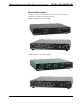
iMedia Receiver with Video & Mic Input Crestron IM-RXV1-M & IM-RXV3-M Physical Description This section provides information on the connections, controls and indicators available on your IM-RXV1-M and IM-RXV3-M. IM-RXV1-M Physical Views (Front and Rear) IM-RXV3-M Physical Views (Front and Rear) 6 • iMedia Receiver: IM-RXV1-M & IM-RXV3-M Operations & Installation Guide – DOC.
Crestron IM-RXV1-M & IM-RXV3-M iMedia Receiver with Video & Mic Input IM-RXV1-M & IM-RXV3-M Overall Dimensions 8.75 in (22.23 cm) 7.69 in (19.53 cm) 1.62 in (4.10 cm) (Continued on following page) Operations & Installation Guide – DOC.
iMedia Receiver with Video & Mic Input Crestron IM-RXV1-M & IM-RXV3-M IM-RXV1-M & IM-RXV3-M Overall Dimensions (Continued) 1 4 5 7 6 2 8 1 2 3 9 10 11 12 13 3 14 15 16 G Connectors, Controls & Indicators # CONNECTORS1, CONTROLS & INDICATORS 1 IM INPUT & PEAKING CONTROL DESCRIPTION (1) 8-wire RJ-45 female (three on IM-RXV3-M), iMedia input port(s); Connect(s) to IM output port(s) of an (up to three) iMedia transmitter via CresCAT™-IM cable2.
Crestron IM-RXV1-M & IM-RXV3-M iMedia Receiver with Video & Mic Input Connectors, Controls & Indicators (Continued) # CONNECTORS1, CONTROLS & INDICATORS 5 PWR LED 6 RESET BUTTON 7 RELAY OUTPUT (1 – 2), INPUT (1 – 3), IR, G 1 2 1 2 3 DESCRIPTION (Green) indicates power connected to 18 VDC connector. SW-R - (1) Recessed pushbutton for software reset. G IR (1) 9-pin 3.
iMedia Receiver with Video & Mic Input Crestron IM-RXV1-M & IM-RXV3-M Connectors, Controls & Indicators (Continued) # CONNECTORS1, CONTROLS & INDICATORS LAN3 12 GREEN LED PIN 8 (1) 8-wire RJ-45 with two LED indicators; 10BaseT/100BaseTX Ethernet port; Green LED indicates link status; Yellow LED indicates Ethernet activity.
Crestron IM-RXV1-M & IM-RXV3-M iMedia Receiver with Video & Mic Input Connectors, Controls & Indicators (Continued) # CONNECTORS1, CONTROLS & INDICATORS 16 GROUND4 DESCRIPTION (1) 6-32 screw, chassis ground lug. 1. Interface connectors for SPEAKER, AUDIO, RELAY OUTPUT/INPUT/IR/G, and MIC ports are provided with the unit. 2. For iMedia use CreCAT-IM cable or quality CAT5e/CAT6 cable having a maximum delay skew of 15ns per 100m. 3.
iMedia Receiver with Video & Mic Input Crestron IM-RXV1-M & IM-RXV3-M Setup Network Wiring When wiring an iMedia system, consider the following: • Use Crestron Certified Wire. • Use Crestron power supplies for Crestron equipment. • Provide sufficient power to the system. CAUTION: Insufficient power can lead to unpredictable results or damage to the equipment.
Crestron IM-RXV1-M & IM-RXV3-M iMedia Receiver with Video & Mic Input Signal Selection The RGB signal connected to the IM transmitter is delivered to the display device (e.g., projector) via the RGBHV output of an IM receiver. The composite video signal connected to the IM transmitter is delivered to the display device (e.g., projector) via the composite video output of an IM receiver.
iMedia Receiver with Video & Mic Input Crestron IM-RXV1-M & IM-RXV3-M Installation Ventilation The IM-RXV1-M and IM-RXV3-M should be used in a well-ventilated area. To prevent overheating, do not operate this product in an area that exceeds the environmental temperature range listed in the table of specifications. Consider using forced air ventilation and/or incrementing the spacing between units to reduce overheating.
Crestron IM-RXV1-M & IM-RXV3-M iMedia Receiver with Video & Mic Input Hardware Hookup Make the necessary connections as called out in the illustration that follows this paragraph. Apply power after all connections have been made. When making connections to the IM-RXV1-M and IM-RXV3-M, consider the following: • Use Crestron power supplies for Crestron equipment. • The included cable cannot be extended.
iMedia Receiver with Video & Mic Input Crestron IM-RXV1-M & IM-RXV3-M System Configuration Have a question or comment about Crestron software? Answers to frequently asked questions (FAQs) can be viewed in the Online Help section of the Crestron website. To post a question or view questions you have submitted to Crestron’s True Blue Support, log in at http://support.crestron.com. First-time users will need to establish a user account.
Crestron IM-RXV1-M & IM-RXV3-M iMedia Receiver with Video & Mic Input Uploading and Upgrading Crestron recommends using the latest programming software and that each device contains the latest firmware to take advantage of the most recently released features. However, before attempting to upload or upgrade it is necessary to establish communication. Once communication has been established, files (for example, programs or firmware) can be transferred to the device).
iMedia Receiver with Video & Mic Input Crestron IM-RXV1-M & IM-RXV3-M • Use the Address Book in the Crestron Toolbox to create an entry for the IM-RXV1-M or IM-RXV3-M with the IM-RXV1-M or IM-RXV3-M’s TCP/IP communication parameters. • Display the “System Info” window (click the IM-RXV1-M or IM-RXV3-M entry. icon) and select the Firmware Firmware files may be distributed from programmers to installers or from Crestron to dealers.
Crestron IM-RXV1-M & IM-RXV3-M iMedia Receiver with Video & Mic Input Problem Solving Troubleshooting The following table provides corrective action for possible trouble situations. If further assistance is required, please contact a Crestron customer service representative. IM-RXV1-M and IM-RXV3-M Troubleshooting TROUBLE PWR LED does not illuminate. No video output displayed. POSSIBLE CAUSE(S) CORRECTIVE ACTION Not receiving power.
iMedia Receiver with Video & Mic Input Crestron IM-RXV1-M & IM-RXV3-M Further Inquiries If you cannot locate specific information or have questions after reviewing this guide, please take advantage of Crestron's award winning customer service team by calling the Crestron corporate headquarters at 1-888-CRESTRON [1-888-273-7876]. For assistance in your local time zone, refer to the Crestron website (http://www.crestron.com/offices) for a listing of Crestron worldwide offices.
Crestron IM-RXV1-M & IM-RXV3-M iMedia Receiver with Video & Mic Input Software License Agreement This License Agreement (“Agreement”) is a legal contract between you (either an individual or a single business entity) and Crestron Electronics, Inc. (“Crestron”) for software referenced in this guide, which includes computer software and as applicable, associated media, printed materials and “online” or electronic documentation (the “Software”).
iMedia Receiver with Video & Mic Input Crestron IM-RXV1-M & IM-RXV3-M If You are a business or organization, You agree that upon request from Crestron or its authorized agent, You will within thirty (30) days fully document and certify that use of any and all Software at the time of the request is in conformity with Your valid licenses from Crestron of its authorized agent.
Crestron IM-RXV1-M & IM-RXV3-M iMedia Receiver with Video & Mic Input Return and Warranty Policies Merchandise Returns / Repair Service 1. No merchandise may be returned for credit, exchange or service without prior authorization from CRESTRON. To obtain warranty service for CRESTRON products, contact an authorized CRESTRON dealer. Only authorized CRESTRON dealers may contact the factory and request an RMA (Return Merchandise Authorization) number.
Crestron Electronics, Inc. 15 Volvo Drive Rockleigh, NJ 07647 Tel: 888.CRESTRON Fax: 201.767.7576 www.crestron.com Operations & Installation Guide – DOC. 6593A (2018247) 07.07 Specifications subject to change without notice.