DC-300A II CHANNEL 1 POWER I0C CHANNEL 2 30 30 40 40 20 10 50 20 10 50 0 0 Some models may be exported under the name Amcron.® ® Applies only to 120 VAC North American units. © 1996 by Crown International, Inc., P.O. Box 1000, Elkhart, Indiana 46515-1000 U.S.A. Telephone: 219-294-8000. The DC-300A II is produced by the Professional Audio Division of Crown International, Inc.
3 YEAR THREE YEAR FULL WARRANTY 3 YEAR WORLDWIDE NORTH AMERICA SUMMARY OF WARRANTY The Crown Audio Division of Crown International, Inc., 1718 West Mishawaka Road, Elkhart, Indiana 46517-4095 U.S.A.
The information furnished in this manual does not include all of the details of design, production, or variations of the equipment. Nor does it cover every possible situation which may arise during installation, operation or maintenance. If your unit bears the name “Amcron,” please substitute it for the name “Crown” in this manual. If you need special assistance beyond the scope of this manual, please contact our Technical Support Group. Crown Audio Division Technical Support Group 57620 C.R.
DC-300A II Power Amplifier CONTENTS 1 Welcome ............................................................................ 7 1.1 Unpacking ................................................................... 7 1.2 Features ...................................................................... 7 2 Facilities ............................................................................ 8 3 Installation ......................................................................... 9 3.1 Mounting ....................
DC-300A II Power Amplifier ILLUSTRATIONS 1.1 2.1 3.1 3.2 3.3 3.4 3.5 3.6 3.7 3.8 3.9 3.10 5.1 6.1 6.2 6.3 6.4 6.5 6.6 6.7 6.8 6.9 7.1 DC-300A II ................................................................................ 7 Facilities .................................................................................... 8 Mounting Dimensions ............................................................... 9 System Connection .................................................................
DC-300A II Power Amplifier Rev.
DC-300A II Power Amplifier CHANNEL 1 POWER I0C CHANNEL 2 30 30 40 40 20 10 50 0 20 10 50 0 Fig. 1.1 DC-300A II 1 Welcome Congratulations on purchasing a Crown DC-300A II. Your amplifier is designed to provide reliable operation with a variety of loads. It is a versatile choice for use in studios, laboratories, public facilities and on the road. And the sonic excellence of the DC-300A II makes it a very good choice for your personal listening pleasure.
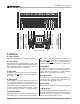
DC-300A II Power Amplifier CHANNEL 1 POWER I0C CHANNEL 2 30 30 40 40 20 10 50 20 10 50 0 A B C D C E F OUTPUT OUTPUT CHANNEL 2 CHANNEL 1 2 INPUT 1 G D 0 H I H G LINE FUSE AC DUAL MONO ® INTERNATIONAL, INC. ELECTRONIC EQUIPMENT ELKHART, IN 46517 MADE IN U.S.A. SERIAL NUMBER 0000 000000 Fig. 2.1 Facilities 2 Facilities A. Power Indicator This indicator glows when the amplifier is turned on. B. Power Switch This push button turns the DC-300A II on and off.
DC-300A II Power Amplifier 3 Installation Your amplifier is designed for standard 19 inch (48.3 cm) rack mounting. Before mounting, determine whether you need to change the amplifier’s internal settings for your application. Your amplifier’s internal settings make it possible to change the input sensitivity from the default 26 dB gain to a sensitivity of 0.775 volts. If you need to operate your amplifier with an input sensitivity of 0.
DC-300A II Power Amplifier – – + + CHANNEL 2 CHANNEL 1 DUAL MODE OUTPUT OUTPUT CHANNEL 2 CHANNEL 1 2 INPUT 1 LINE FUSE AC DUAL MONO CHANNEL 1 INTERNATIONAL, INC. ELECTRONIC EQUIPMENT ® ELKHART, IN 46517 MADE IN U.S.A. SERIAL NUMBER 0000 000000 CHANNEL 2 MIXER DC-300A II AMP DUAL MONO – + CHANNEL 2 (+) CHANNEL 1 (+) BRIDGE-MONO MODE (METHOD 1) OUTPUT OUTPUT CHANNEL 2 CHANNEL 1 2 INPUT 1 LINE FUSE AC DUAL MONO CHANNEL 1 INTERNATIONAL, INC.
DC-300A II Power Amplifier outputs will receive the channel 1 input. The channel 2 output is inverted so it can be bridged with channel 1. dB 0 –5 There are two different ways to connect Bridge-Mono wiring. The most common method is to connect the positive (+) output of channel 1 to the positive (+) loudspeaker lead, and the positive (+) output of channel 2 to the negative (–) loudspeaker lead (see Figure 3.2). The negative amplifier outputs are not used.
DC-300A II Power Amplifier A third problem to avoid is hum. The two most common sources of hum in an audio system are inductive coupling and ground loops. Inductive coupling can occur when input cables are subjected to a magnetic field from a power cord or power transformer. One way to prevent inductive coupling is to lace the input cables together along their length and route them as far away as possible from power transformers and power cords.
DC-300A II Power Amplifier 3. Draw a line through the two points with a pencil, and continue until it intersects the “Source Resistance” line. 4. On the “2-Cond. Cable” line, mark the length of cable run. 5. Draw a pencil line from the mark on the “Source Resistance” line through the mark on the “2-Cond. Cable” line, and on to intersect the “Annealed Copper Wire” line. 6. The required wire gauge for the selected wire length and damping factor is the value on the “Annealed Copper Wire” line.
DC-300A II Power Amplifier Littlefuse 361000 series. If the loudspeaker is only susceptible to damage caused by prolonged overload (such as overheating), use a fuse or circuit breaker having the same slow thermal response as the loudspeaker itself (such as a slow-blow fuse). The nomograph in Figure 3.9 shows fuse size versus loudspeaker peak power rating. It can be used to determine the size of the required fuse. 1.0 1.2 1.6 20 3000 15 2000 1000 8 9 Answer: Fuse = 1.5 A 150 2 100 80 1.
DC-300A II Power Amplifier 4 Operation 4.1 Precautions 4.2 Indicators Your amplifier is protected from all external faults. Even so, you should take the following precautions: Your amplifier has three front panel indicators. The yellow power indicator glows when the amplifier is turned on and the unit is receiving power. 1.
DC-300A II Power Amplifier The input stages are protected from overload by series resistors. The unit also features a controlled slew rate and the JTS limiter that protect the amplifier from highfrequency blowups. A thermal switch is mounted on each heat sink to protect your amplifier against overheating. If either heat sink becomes too hot, the AC mains power will be interrupted until the temperature falls to a safe level and the unit resets itself.
DC-300A II Power Amplifier 5 Technical Information 5.1 Principles of Operation The DC-300A II has input amplifiers that are powered by zener-regulated power supplies. The bias regulators are also powered by zener-regulated current sources with the result that line voltage variations do not cause noise or distortion due to misbiasing. bias current in the output transistors. The benefit is maximum efficiency, minimum crossover notch distortion and minimum thermal dissipation at idle.
DC-300A II Power Amplifier 6 Specifications Note: The following specifications apply to units configured for 120 VAC, 60 Hz operation in Dual mode with 8 ohm loads and an input sensitivity of 26 dB gain unless otherwise specified. Performance Frequency Response: ±0.1 dB from DC to 20 kHz at 1 watt (see Figure 6.9). Phase Response: +0/–15 degrees from DC to 20 kHz at 1 watt (see Figure 6.5). Signal-to-Noise Ratio: (20 Hz to 20 kHz) At least 110 dB below rated maximum average power (see Figure 6.8).
DC-300A II Power Amplifier Construction Dimensions: 19 inch (48.3 cm) standard rack mount width (EIA std. RS-310-B); 7 inch (17.8 cm) height; 10.5 inch (26.7 cm) depth behind front mounting surface; 0.625 inch depth in front of mounting surface. chassis and top cover. Chassis: All aluminum construction for maximum heat conduction and minimum weight. Heavy aluminum front panel is a single extrusion. Weight: Net weight is 40 pounds, 11 ounces (18.5 kg); Shipping weight is 45 pounds, 0 ounces (20.3 kg).
DC-300A II Power Amplifier 1 0.1 Zo (ohms) 0.01 TO DC 0.001 0.1 1 10 100 1K 10 K 100 K FREQUENCY (Hz) Fig. 6.2 Nominal Output Impedance 90 60 Zo (degrees) 30 0 10 100 1K 100 K 10 K FREQUENCY (Hz) Fig. 6.3 Nominal Output Phase Angle (1 amp) 10000 1000 dB 100 10 TO DC 1 10 100 1K FREQUENCY (Hz) Fig. 6.
DC-300A II Power Amplifier 15 0 –15 Phase Shift (degrees) –30 16 ohms –45 8 ohms 4 ohms –60 0.1 1 10 100 1K 100 K 10 K FREQUENCY (Hz) Fig. 6.5 Nominal Phase Response (1 Watt) –60 –80 dB –100 –120 1 10 100 1K 100 K 10 K FREQUENCY (Hz) Fig. 6.6 Nominal Crosstalk (Channel 1 at 150 watts and Channel 2 at Maximum Output) 70% 60% EFFICIENCY 2 50% 1 40% 30% 1 1 SINGLE CHANNEL DRIVEN 2 BOTH CHANNELS DRIVEN 10 100 1K 10 K 100 K FREQUENCY (Hz) Fig. 6.
DC-300A II Power Amplifier 1000 100 nV Hz 10 1 0.1 1 10 100 1K 10 K 100 K FREQUENCY (Hz) Line frequency harmonics plotted to the tenth order. The 150 watt output is indicated by the dot at the top of the extended dashed line. Spectrum total is equivalent to 1.3 microvolts input noise over a 20 Hz to 20 kHz bandwidth. Fig. 6.8 Nominal Noise Spectrum 1 0 dB 16 ohms –1 8 ohms –2 4 ohms 8 ohms with Level Control at 12:00 –3 0.1 1 10 100 1K 10 K FREQUENCY (Hz) Fig. 6.
DC-300A II Power Amplifier 7 Internal Settings From the factory, your amplifier is configured for an input sensitivity of 26 dB gain. For the DC-300A II, this setting requires an input signal of 1.75 volts (±2%) to drive the amplifier to full output. You may optionally configure the unit for an input sensitivity of 0.775 volts (0 dBm) for full rated output power. To change your amplifier’s input sensitivity to 0.775 volts, the chassis of the unit must be opened.
DC-300A II Power Amplifier 8 Service This unit has very sophisticated circuitry which should only be serviced by a fully trained technician. This is one reason why each unit bears the following label: CAUTION: To prevent electric shock, do not remove covers. No user serviceable parts inside. Refer servicing to a qualified technician. sent “UPS ground.” (If the unit is under warranty, you may send it C.O.D. for the cost of freight via UPS ground.) The factory will return it via UPS ground.
DC-300A II Power Amplifier Crown Factory Service Information Shipping Address: Crown International, Inc., Factory Service, 57620 C.R.