DCi Series – Network Models Operation Manual DCi 8|600N DCi 8|300N DCi 4|600N DCi 4|300N DCi 2|600N DCi 2|300N DCi 4|1250N DCi 2|1250N DCi 4|2400N DCi 2|2400N Product Registration: Register your new product at http://warranty.harmanpro.com. Obtaining Other Language Versions: To obtain information in another language about the use of this product, please contact your local Crown Distributor. If you need assistance locating your local distributor, please contact Crown at 574-294-8000 or visit www.crownaudio.
DriveCore Install Network Series Power Amplifiers Important Safety Instructions 1. Read these instructions. WATCH FOR THESE SYMBOLS: 2. Keep these instructions. The lightning bolt triangle is used to alert the user to the risk of electric shock. 3. Heed all warnings. 4. Follow all instructions. The exclamation point triangle is used to alert the user to important operating or maintenance instructions. 5. Do not use this apparatus near water. 6. Clean only with a dry cloth. 7.
DriveCore Install Network Series Power Amplifiers DECLARATION OF CONFORMITY Issued By: H ARMAN International 1718 W. Mishawaka Rd. Elkhart, IN 46517 U.S.A.
DriveCore Install Network Series Power Amplifiers Table of Contents Important Safety Instructions ................................................................................................................................................................................ 2 Declaration of Conformity...................................................................................................................................................................................... 3 Table of Contents.......
DriveCore Install Network Series Power Amplifiers Welcome Thank you for purchasing a new Crown DriveCore™ Install Network Series installation amplifier, one in a complete line of high-performance amplifiers based on exclusive DriveCore technology.
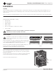
DriveCore Install Network Series Power Amplifiers Installation Unpacking Unpack your amplifier and inspect for any damage that may have occurred during transit. If damage is found, notify the shipping company immediately. Only you can initiate a claim for shipping damage, though Crown will be happy to help as needed. If the product arrived showing signs of damage, save the shipping carton for the shipper’s inspection.
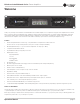
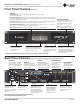
DriveCore Install Network Series Power Amplifiers Front Panel Features (All Models) Indicators: Fault Indicator (red): Flashes when the amplifier output channel has stopped operating. (See Page 50 Troubleshooting) Thermal Indicator (red): Illuminates when the channel reaches 80 degrees Celsius, indicating the onset of protection compression. If the temprature continues to rise, the amplifier output will shut off at 98 degrees Celsius and remain off until a safe operating temperature is present.
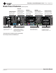
DriveCore Install Network Series Power Amplifiers Back Panel Features (2|2400N, 4|2400N) GPIO/AUX Cooling Fan Outlet Outlets for cooling air flow. Do not block or cover these outlets. Power Cord Connector 32A PowerCon® AC inlet, 100-240V. The DCi2|2400N uses a 20A IEC connector. 8-pin block connector combines the 2-in, 2-out GPIO (see Page 27) with the SLEEP and AMP STATUS pin from the AUX circuit (see Page 32).
DriveCore Install Network Series Power Amplifiers Hardware Setup and Configuration Figure 3 Wire Input Connectors Crown recommends using pre-built or professionally wired balanced cables (two-conductor plus shield). Balanced wiring provides better rejection of unwanted noise and hum; however, unbalanced line may also be used. Use 6-pin plug-in cable ends at the amp input connectors. A male connector is supplied for each input of your model of amplifier.
DriveCore Install Network Series Power Amplifiers Hardware Setup and Configuration Connect to AC Mains Connect your amplifier to the AC mains power source (power outlet) using the supplied AC power cord set. First, connect the IEC end of the cord set to the IEC connector on the amplifier; then, plug the other end of the cord set to the AC mains. WARNING: The third prong of this connector (ground) is an important safety feature.
DriveCore Install Network Series Power Amplifiers Software Setup Connect Loudspeakers and Configure for Loudspeaker Load Determine load impedances and power requirements Before making any connections, carefully check and review the total impedance for loudspeaker systems to be connected to each amplifier output.
DriveCore Install Network Series Power Amplifiers NetSetter Introduction The HiQnet NetSetter is a software tool which enables you to discover HiQnet devices and reconfigure network settings in real-time for each device. Its function is to configure a system of devices to interoperate correctly on the same network and resolve conflicts quickly and easily. NetSetter Window Figure 7 The top of the NetSetter page list overall operational functions that are available.
DriveCore Install Network Series Power Amplifiers At the bottom of the NetSetter window is an informational section that list the amount of discovered devices and the IP address of the DHCP Server. There is also information regarding the PC HiQnet Address, IP Address, and Subnet Mask. There are four buttons that perform the following functions: • Clear Container - Resets the Container / Position Venue data of the selected device.
DriveCore Install Network Series Power Amplifiers IP Address Displays the IP address of the discovered device A valid IP address may be edited inline. If the edited value scopes the device out of the current Display filter, it will not be visible. Devices discovered with a conflicting IP Address A discovered device with an IP Address that conflicts with one that has already been discovered will be displayed in red.
DriveCore Install Network Series Power Amplifiers • When the device is selected and highlighted in orange the field is represented in red. • The HiQnet address is not displayed, instead a dash is displayed as grayed out. Devices not discoverable at the IP level A device which is not discoverable at the IP level (invalid IP address etc) will not be able to report a HiQnet address.
DriveCore Install Network Series Power Amplifiers • The device is discoverable at the MAC Address level • The device has a valid and unique IP Address (manual or DHCP / Auto-IP) • The device has a HiQnet address which conflicts with another device which has already been discovered by NetSetter Locked - The ‘Discovered’ status is determined by the following conditions: • The device is discoverable at the MAC Address level • The device has a valid and unique IP Address (manual or DHCP / Auto-IP) • The device
DriveCore Install Network Series Power Amplifiers Devices not discoverable at the IP or HiQnet level A device which is not discoverable at the IP level (invalid IP address etc) or HiQnet address level (HiQnet address conflict etc) will not be able to report its Device Name.
DriveCore Install Network Series Power Amplifiers Offline/Online Audio Architect has two define modes of operation: Online and Offline. Offline operation allows the system to be configured without real time changes to the system. In this mode, changes have to be sent to the edited device. In Online mode, changes to amplifiers are made real time.
DriveCore Install Network Series Power Amplifiers Each amplifier can be dragged into the room window. Each device will have a IP address listed on the left of the amplifier and a Name ID on the right on the amplifier. The Name ID can be edited in the properties menu at the bottom of the page. The number to the left of Name ID is the HiQnet Device Address. The green circle only indicates that the amplifier has been discovered on the network.
DriveCore Install Network Series Power Amplifiers Set-up and System Configuration Amplifier Mode Settings Figure 13 Figure 13 (above) shows the DriveCore Install 2 channel configuration page. The 4 and 8 channel amplifier configuration pages have the same feature set. The DriveCore Install Network amplifier includes Digital Signal Processing (DSP), multiple input/output routing options and a comprehensive diagnostics feature set. All of these features can be adjusted in from the configuration page.
DriveCore Install Network Series Power Amplifiers Set-up and System Configuration Cascading Inputs Cascading the analog inputs, or "Y-ing channels", gives more flexibility to the installation of this amplifier (See Figure 15). One input can be used to drive some or all of the amplifier outputs. NOTE: By cascading the inputs, the corresponding input DSP functions for individual channels will be removed and only the output DSP functions will be available (See Figure 16). Figure 15 Use the "Y 1+2" etc.
DriveCore Install Network Series Power Amplifiers Set-up and System Configuration Bridge Mono Operation The DriveCore Install amplifier outputs can be bridged to increase the power and voltage available at the output of the amplifier. The amplifier can be bridged in the Amplifier Mode window. By selecting the bridging option, only the first input channel will need to be wired. (See Figure 17). Low-Z and High-Z options are still available.
DriveCore Install Network Series Power Amplifiers Set-up and System Configuration Low-Z (8Ω, 4Ω or 2Ω) Output Operation Typical input and output wiring, along with Audio Architect software settings are shown in Figure 19. INPUTS: Connect the input with wiring in place for each channel. If the same signal is to drive both outputs of a channel pair (“mono”), the input signal can be sent to adjacent amplifier channels.
DriveCore Install Network Series Power Amplifiers Set-up and System Configuration Bridge Mode (16Ω, 8Ω, or 4Ω) Output Operation Typical input and output wiring, along with software settings are shown in Figure 21. INPUT WIRING: If using analog inputs, it is only necessary to wire the odd number inputs. If using the BLU link input, it is important to understand that BLU link is a digital audio bus and cannot be routed through a network switch or router.
DriveCore Install Network Series Power Amplifiers Set-up and System Configuration Dual Mode Hi-Z (70Vrms/100Vrms) Mode Typical input and output wiring, along with software settings are shown in Figure 23. A 35Hz high pass filter is selected automatically when the amplifier channel is in Hi-Z or Bridged Hi-Z mode. Remember, DCi amplifiers allow each channel Hi-Z or Low-Z mode of operation to be selected independently, while 70Vrms/100Vrms selection is global.
DriveCore Install Network Series Power Amplifiers Set-up and System Configuration Bridge Mode Hi-Z (140Vrms/200Vrms) INPUTS: Connect the input to the odd-numbered channels (1,3,5,7) only. Even-numbered inputs are disabled when the Bridge Mono mode is active. OUTPUTS: Connect the speaker across the positive terminals of each channel pair. Do not use the negative terminals of the channel pair when the pair is being operated in Bridge Mono mode.
DriveCore Install Network Series Power Amplifiers General Purpose In/Out Control Port DriveCore Install Network amplifiers come with a 2-in, 2-out General Purpose In/Out (GPIO) control port in the form of either a 6 position RJ-11 connector (2|300N, 2|600N, 2|1250N, 4|300N, 4|600N, 4|1250N, 8|300N, 8|600N) or a block connector (2|2400N, 4|2400N). The Control Port has multiple functions and uses which include preset selection and gain control, among others.
DriveCore Install Network Series Power Amplifiers General Purpose In/Out Control Port Figure 27 Control Port Configuration Page In the Venue Explorer, select and expand the device for a list of objects. Expand an object for a list of state variables (SV’s) within the object. A state variable can be added to the control port input assignment by clicking and dragging with the mouse into the “Parameter Assignment” tab for either input 1 or 2.
DriveCore Install Network Series Power Amplifiers General Purpose In/Out Control Port Additional state variables can be added to a given control port input by selecting the SV and dragging on top of a previously assigned row of the desired input. However, once an SV has been assigned and the MODE has been set, any subsequent SV that is added must function in the same MODE. Up to 40 SV’s can be assigned to a given input.
DriveCore Install Network Series Power Amplifiers General Purpose In/Out Control Port Configuration of the Control Port Outputs 2 outputs: Binary only. • There is a polarity control on each output so that it may function as active-high or active-low • Output Mode 1 - Manual: Controlled directly by the output enable button • Output Mode 2 - Report Errors: Active when any enabled error is reported. The indicator will stay on for up to 60 seconds after the error is cleared.
DriveCore Install Network Series Power Amplifiers General Purpose In/Out Control Port Figure 30 Control Port Output Configuration NOTE: In all modes, the polarity of the binary output can be toggled under the OUTPUT POLARITY tab, where “Normal” or “Inverted” can be selected.
DriveCore Install Network Series Power Amplifiers Aux Port/Sleep/Amp Status 2|300N, 2|600N, 2|1250N, 4|300N, 4|600N, 4|1250N, 8|300N, 8|600N AUX Port The AUX port can be used for basic monitoring of the amplifier and for remote standby. The port is a 3 pin block connector with pin-2 used as ground. Sleep The amplifier can be put to sleep by connecting pins 1 and 2 together on the AUX port.
DriveCore Install Network Series Power Amplifiers BLU link BLU link BLU link is an audio bus found on the DriveCore Install Network amplifier series. It carries 256 channels of audio at 48kHz, and 128 channels at 96kHz, both at 24bit. When connected in a loop, it has redundancy, allowing any one BLU link cable to break while still maintaining audio. BLU link Specification • Based on Gigabit Ethernet technology • 100m over CAT5e cable between each point. • >100m using fibre converters.
DriveCore Install Network Series Power Amplifiers BLU link Any multi-transport combination NOT specifically listed above is not allowed in Soundweb London systems (without being forced to use analog interconnects between transports). For example, BLU link + AVB + CobraNet is NOT allowed, because the AVB and CobraNet networks would each be synced to different clocks—their own. Mastership is negotiated between all the devices on the ring, and change to the ring will trigger the negotiation to be started.
DriveCore Install Network Series Power Amplifiers BLU link Figure 32 BLU link Input Channel Assignment BLU link Routing Double-clicking on the BLU link Routing button opens the BLU link channel assignment dialogue. The DCi-N amplifiers have 8 'slots' (labeled A through H) available for receiving a BLU link audio stream, which can then be sent to any one of the channels in the amplifier via the Source Routing panel.
DriveCore Install Network Series Power Amplifiers BLU link Figure 33 BLU link Output Configuration The analog inputs for the DriveCore Install Network amplifier provide additional flexibility when for the BLU link digital audio bus.
DriveCore Install Network Series Power Amplifiers Advanced Operation Introduction Your DriveCore Install amplifier has a wide variety of onboard Digital Signal Processing (DSP). HiQnet Audio Architect software lets you adjust the DSP settings, such as filter slope, compression ratio, EQ frequency bands, and so on. A preset is a group of DSP settings that configure the amp for a specific application. For example, you might use one preset that optimizes the amp’s DSP for a JBL tri-amplified speaker setting.
DriveCore Install Network Series Power Amplifiers Advanced Operation Speaker Tunings Crown and JBL engineers have designed DriveCore Install DSP settings that are optimized for various JBL loudspeakers. Speaker tunings can be downloaded at the following website: www.jblpro.com. An improved speaker tuning approach has been developed for the DriveCore Install Network Series. The system is software library based rather than device preset based.
DriveCore Install Network Series Power Amplifiers Advanced Operation Advanced STP functions are available to create/modify speaker tunings. Holding CTRL-ALT-SHFT while double-clicking the speaker tuning icon opens the advanced panel. See Figure 25 Figure 35 Basic Speaker Tuning Panel The advanced panel includes every parameter implemented in a speaker tuning : 1. All parameters from basic panel (Recall, Store, Load, Delete, Mfr Name, Model, Band) 2.
DriveCore Install Network Series Power Amplifiers Advanced Operation JBL host Screen Array Library This library is included with Audio Architect at install. The tunings in this library were developed and validated against previous same tunings for Crown DSI amplifiers. It is read-only to prevent over-write. At any time, a user can load this library to access reference JBL tunings for these devices. User Libraries At any time, the user may save the current working library to a custom user library file.
DriveCore Install Network Series Power Amplifiers Advanced Operation Software-Controllable Onboard DSP Crown DriveCore Install Network amplifier have Digital Signal Processing built into the amplifier. When you use a DriveCore Install Network amp, the loudspeaker processors, crossovers, limiters and delays are in the onboard DSP – so discrete rack mount devices are not needed. This drastically cuts setup time, commissioning, rack space and costs.
DriveCore Install Network Series Power Amplifiers Advanced Operation Input Level, Faders, Mute, Link, I/O Level Meters, and Indicators Figure 37 This panel is on the left side of the DriveCore Install Network main control panel shown above. Channels 1, and 2 Level Controls set the input signal level of each channel. Each channel can be muted, and both faders can be linked with the Link button. Input Signal Level Meter (green) The measurement range is from 0dBFS to –40dBFS with 0.5dB resolution.
DriveCore Install Network Series Power Amplifiers Advanced Operation Input Signal Router Each channel of the DriveCore Install signal processing has an Input Signal Router that lets you choose the audio signal that will be used by the channel. • Analog Audio: This selection set up the input router for analog sources. Each output channel will select its corresponding analog input. Choices for the Analog Audio input are Channel 1, Channel 2, or a sum of Channels 1 and 2.
DriveCore Install Network Series Power Amplifiers Advanced Operation Source Routing/Configuration Figure 39 Quick Start Selection button at the bottom of the page. Manual configuration of Threshold, Attack, Release, and Depth of Cut can be adjusted in this page. These items are defined as follows: • Threshold – Sets the level in dB below which the secondary input will be engaged. • Attack – Defined as the time it takes for the secondary source to engage. This can range from 0.1 seconds to 1.
DriveCore Install Network Series Power Amplifiers Advanced Operation Input Delay and Driver/Output Delay Input delay includes up to 2 seconds of delay. Output delay is typically used for driver alignment. Up to 0.1 seconds of output delay is provided. See Figure 40 Figure 40 Input/Output Equalization These screens let you adjust channel equalization for up to 8 frequencies. You can select filter type, frequency, gain, and bandwidth in octaves or Q as set by the user preferences in Audio Architect.
DriveCore Install Network Series Power Amplifiers Advanced Operation Crossover Filters The Crossover section lets you use infinite impulse response (IIR) Crossover filter. Each audio channel has three separate places where filters can be placed in the system: input EQ, Crossover, and Output EQ. Up to 16 EQ filters per channel are available, plus crossover filters. Each filter has up to +/-24dB of gain.
DriveCore Install Network Series Power Amplifiers Advanced Operation LevelMax™ Suite This is a suite consisting of a peak voltage limiter, RMS power limiter, clip limiter and transducer thermal limiter. First you will set the mode to automatic or advanced: See Figure 43. • Automatic mode: The software determines the best settings based on the signal characteristics. You can modify only the RMS threshold, Speaker Thermal threshold and time constant. Everything else is set automatically.
DriveCore Install Network Series Power Amplifiers Signal Path Figure 44 Signal Path page 48 Operation Manual
DriveCore Install Network Series Power Amplifiers Per Channel Settings Channel Attenuators Each channel is supplied with a logrithmic 21-position detented input attenuator. Use a flat-blade screwdriver to set input level. Attenuation is from -95 dB (full counter-clockwise) to 0 dB (full clockwise). For gain structure purposes, it is important to note that attenuators are at the end of the DSP signal chain. Position 0 1 2 3 4 5 6 7 8 9 10 Typical Attenuation 0 -0.
DriveCore Install Network Series Power Amplifiers Protection System Thermal Indicator If the amplifier becomes too hot for safe operation, the channel that is generating too much heat will be shut down until the temperature drops below the thermal limit. The front-panel thermal indicator will illuminate at 80 degrees Celsius, indicating the onset of compression affecting the audio signal.
DriveCore Install Network Series Power Amplifiers Troubleshooting CONDITION: Power indicator is off. Mains indicator is on. POSSIBLE REASON • The amplifier’s Power switch is off. “Off/Flashing/On” above means that the LED can be off, or flashing, or on. CONDITION: Power indicator is off. Mains indicator is off. POSSIBLE REASON • The power supply fuse has tripped. • The amplifier has lost AC Power. • The amplifier is not plugged in to the power receptacle. CONDITION: Power indicator is flashing.
DriveCore Install Network Series Power Amplifiers Troubleshooting CONDITION: Distorted sound. POSSIBLE REASON: • Load is wired incorrectly or Stereo/Bridge mode switch is set incorrectly. Check both. • Input is overloaded by a signal level that is too high. Turn down your amplifier level controls, or turn down the input signal, until the clip light goes out. Note: If the signal sounds distorted even though the Clip LED is off, the input signal may be distorted before it reaches the amplifier input.
DriveCore Install Network Series Power Amplifiers Troubleshooting CONDITION: No input signal. Signal indicator is not flashing even though audio is applied, and the channel is ready.. POSSIBLE REASON: • Input signal level is very low. “Off/Flashing/On” above means that the LED can be off, or flashing, or on. CONDITION: Bridge LED is lit. POSSIBLE REASON: • Amplifier is in Bridge Mono mode.
DriveCore Install Network Series Power Amplifiers DCi Specifications Bridge Mono Mode - All Channels Driven DCi Network Model 4Ω 8Ω 16Ω 140Vrms 200Vrms 2|300N 300W 600W 600W 600W 600W 2|600N 600W 1200W 1200W 1200W 1200W 4|300N 300W 600W 600W 600W 600W 4|600N 600W 1200W 1200W 1200W 1200W 8|300N 300W 600W 600W 600W 600W 8|600N 600W 1200W 1200W 1200W 1200W 2|1250N 2500W 2500W 2500W 2500W 2500W 4|1250N 2500W 2500W 2500W 2500W 2500W 2|2400N 4200W 4800W 38
DriveCore Install Network Series Power Amplifiers DCi Specifications Performance Specifications 2|300N 2|600N 4|300N 4|600N 8|300N 8|600N Voltage Gain (at maximum level setting) 4/8Ω, 70Vrms and 100Vrms Operation 34dB Frequency Response (8Ω, 20Hz - 20kHz) ±0.25dB BLU link Signal-to-Noise Ratio (ref. rated power, (8Ω, 20Hz - 20kHz) >108dB Total Harmonic Distortion (at full rated power, from 20Hz - 20kHz) 0.35% Analog Input Signal to Noise Ratio (ref.
DriveCore Install Network Series Power Amplifiers AC Power Draw and Thermal Dissipation AC Power Draw and Thermal Dissipation: Pink noise 12dB crest factor, bandwidth limited 22Hz to 22kHz. Typical line impedance used. Data based on all channels driven. DCi 2|300N - Bridge 120 VAC / 60 Hz Condition Load "Line current (amps)" watts BTU At Idle Awake N/A 0.6 67 229 4Ω 1.1 86 8Ω 1.4 88 16Ω 1.4 140V (32.67Ω) 200V (66.
DriveCore Install Network Series Power Amplifiers AC Power Draw and Thermal Dissipation AC Power Draw and Thermal Dissipation: Pink noise 12dB crest factor, bandwidth limited 22Hz to 22kHz. Typical line impedance used. Data based on all channels driven. DCi 2|600N - Bridge 120 VAC / 60 Hz 230 VAC / 50 Hz Condition Load "Line current (amps)" At Idle Awake N/A 0.6 71 241 61 0.4 66 226 57 4Ω 1.4 90 308 78 0.
DriveCore Install Network Series Power Amplifiers AC Power Draw and Thermal Dissipation AC Power Draw and Thermal Dissipation: Pink noise 12dB crest factor, bandwidth limited 22Hz to 22kHz. Typical line impedance used. Data based on all channels driven. DCi 2|1250N - Bridge 120 VAC / 60 Hz Condition Load "Line current (amps)" watts BTU At Idle Awake N/A 0.
DriveCore Install Network Series Power Amplifiers AC Power Draw and Thermal Dissipation AC Power Draw and Thermal Dissipation: Pink noise 12dB crest factor, bandwidth limited 22Hz to 22kHz. Typical line impedance used. Data based on all channels driven. DCi 2|2400N - Bridge 120 VAC / 60 Hz Condition Load "Line current (amps)" watts BTU At Idle Awake N/A 1.8 179 4Ω 10.7 8Ω 7.3 16Ω 4.
DriveCore Install Network Series Power Amplifiers AC Power Draw and Thermal Dissipation AC Power Draw and Thermal Dissipation: Pink noise 12dB crest factor, bandwidth limited 22Hz to 22kHz. Typical line impedance used. Data based on all channels driven. DCi 4|300N - Bridge P1-32 120 VAC / 60 Hz 230 VAC / 50 Hz Condition Load "Line current (amps)" At Idle Awake N/A 1.0 118 402 101 0.6 118 401 101 4Ω 1.9 152 520 131 1.
DriveCore Install Network Series Power Amplifiers AC Power Draw and Thermal Dissipation AC Power Draw and Thermal Dissipation: Pink noise 12dB crest factor, bandwidth limited 22Hz to 22kHz. Typical line impedance used. Data based on all channels driven. DCi 4|600N - Bridge P1-32 120 VAC / 60 Hz 230 VAC / 50 Hz Condition Load "Line current (amps)" At Idle Awake N/A 1.0 113 387 98 0.6 118 404 102 4Ω 2.7 170 582 147 1.
DriveCore Install Network Series Power Amplifiers AC Power Draw and Thermal Dissipation AC Power Draw and Thermal Dissipation: Pink noise 12dB crest factor, bandwidth limited 22Hz to 22kHz. Typical line impedance used. Data based on all channels driven. DCi 4|1250N - Bridge P1-32 120 VAC / 60 Hz Condition Load "Line current (amps)" watts BTU At Idle Awake N/A 1.6 183 4Ω 8.4 8Ω 8.
DriveCore Install Network Series Power Amplifiers AC Power Draw and Thermal Dissipation AC Power Draw and Thermal Dissipation: Pink noise 12dB crest factor, bandwidth limited 22Hz to 22kHz. Typical line impedance used. Data based on all channels driven. DCi 4|2400N - Bridge P1-32 120 VAC / 60 Hz Condition Load "Line current (amps)" watts BTU At Idle Awake N/A 2.9 318 1086 4Ω 20.5 889 8Ω 14.
DriveCore Install Network Series Power Amplifiers AC Power Draw and Thermal Dissipation AC Power Draw and Thermal Dissipation: Pink noise 12dB crest factor, bandwidth limited 22Hz to 22kHz. Typical line impedance used. Data based on all channels driven. DCi 8300N - Bridge P1-32 120 VAC / 60 Hz Condition Load "Line current (amps)" watts BTU At Idle Awake N/A 1.8 206 4Ω 3.5 8Ω 4.
DriveCore Install Network Series Power Amplifiers AC Power Draw and Thermal Dissipation AC Power Draw and Thermal Dissipation: Pink noise 12dB crest factor, bandwidth limited 22Hz to 22kHz. Typical line impedance used. Data based on all channels driven. DCi 8|600N - Bridge 15004563770 120 VAC / 60 Hz 230 VAC / 50 Hz Condition Load "Line current (amps)" At Idle Awake N/A 1.9 218 744 188 1.0 220 751 189 4Ω 5.4 330 1126 284 2.
DriveCore Install Network Series Power Amplifiers Service Crown products are quality units that rarely require servicing. Before returning your unit for servicing, please contact Crown Technical Support to verify the need for servicing. Warranty is only valid within the country in which the product was purchased. This unit has very sophisticated circuitry which should only be serviced by a fully trained technician.
DriveCore Install Network Series Power Amplifiers Service 4. Use a bold black marker and write the SRA number on three sides of the box. 5. Record the SRA number for future reference. The SRA number can be used to check the repair status. Packing Instructions Important: These instructions must be followed. If they are not followed, HARMAN International, Inc. assumes no responsibility for damaged goods and/or accessories that are sent with your unit. 1.
DriveCore Install Network Series Power Amplifiers Warranty — UNITED STATES ONLY SUMMARY OF WARRANTY Crown International, 1718 West Mishawaka Road, Elkhart, Indiana 46517-4095 U.S.A. warrants to you, the ORIGINAL PURCHASER and ANY SUBSEQUENT OWNER of each NEW Crown product, for three years from the date of purchase by the original purchaser (the “warranty period”) that the new Crown product is free of defects in materials and workmanship.
DriveCore Install Network Series Power Amplifiers Service Return Authorization Request Shipping Address: HARMAN Factory Service, 1718 W. Mishawaka Rd., Elkhart, IN 46517 You may also request a service return authorization at www.crownaudio.
DriveCore Install Network Series Power Amplifiers page 70 Operation Manual
DriveCore Install Network Series Power Amplifiers Operation Manual page 71