
User's Manual


DriveCore Install Network Series Power Amplifiers
Operation Manual
page 8
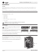
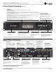
Reset Switch/Circuit Breaker
If the current draw of the amplifier
exceeds safe limits, this breaker
automatically disconnects the power
supply from the AC mains. The switch
resets the circuite breaker.
Input Attenuators
One 21-position detented
potentiometer per channel.
Logarithmic audio taper.
Attenuation range mute to 0 dB.
Input Connectors
One 6-pin plug-in connector per
input pair. High impedance
balanced. (Refer to Page 9).
Output Connectors
One four-pole touch-proof
terminal strip per channel
pair. Accepts up to 10 AWG
wire or terminal forks.
*Warning: Only connect to networks that remain inside the building
Note: This image reflects the DCi 4|2400N back panel
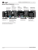
Cooling Fan Outlet
Outlets for cooling air
flow. Do not block or
cover these outlets.
Ethernet*
For monitoring and
control of the amplifier
over Category 5e wiring
through the Audio
Architect software.
GPIO/AUX
8-pin block connector
combines the 2-in, 2-out
GPIO (see Page 27) with
the SLEEP and AMP
STATUS pin from the AUX
circuit (see Page 32).
Power Cord Connector
32A PowerCon
®
AC inlet,
100-240V. The DCi2|2400N uses
a 20A IEC connector.
BLU link*
Input/Output Ring
Up to 256 channels of digital
audio over Category 5e
wiring. Only 60 nodes should
be used in the BLU link Ring.
Back Panel Features (2|2400N, 4|2400N)