ENABLE An IQ System® to Host Computer Interface ©1999 by Crown International, Inc., P.O. Box 1000, Elkhart, Indiana 46515-1000 U.S.A. Telephone: 219-294-8000. The IQ-INT II is produced by the Professional Audio Unit of Crown International, Inc. Trademark Notice: PIPTM is a trademark and Crown,® Amcron® and IQ System® are registered trademarks of Crown International, Inc. Other trademarks are the property of their respective owners. Printed on recycled paper.
THREE YEAR FULL WARRANTY WORLDWIDE NORTH AMERICA SUMMARY OF WARRANTY The Crown Audio Division of Crown International, Inc., 1718 West Mishawaka Road, Elkhart, Indiana 46517-4095 U.S.A.
The information furnished in this manual does not include all of the details of design, production, or variations of the equipment. Nor does it cover every possible situation which may arise during installation, operation or maintenance. If you need special assistance beyond the scope of this manual, please contact our Technical Support Group. Crown Audio Division Technical Support Group Plant 2 SW, 1718 W. Mishawaka Rd., Elkhart, Indiana 46517 U.S.A.
IQ-INT II IQ Interface Important Safety Instructions 1) Read these instructions. 10) Protect the power cord from being walked on or pinched, particularly at plugs, convenience receptacles, and the point where they exit from the apparatus. 2) Keep these instructions. 3) Heed all warnings. 4) Follow all instructions. 11) Only use attachments/accessories specified by the manufacturer. 5) Do not use this apparatus near water. 6) Clean only with a dry cloth. 7) Do not block any ventilation openings.
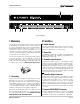
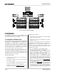
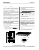
IQ-INT II IQ Interface A ENABLE 1 IN OUT IN 2 OUT IN 3 OUT IN 4 OUT IN 5 OUT IN 6 OUT IN 7 OUT IN 8 OUT COMPUTER RS232 / RS422 1 INPUT OUTPUT 2 WIRING B GND C WIRING 3 1 USE SIDE ACCESS HOLE TO SET BAUD RATE AND OTHER COM SETTINGS. 2 D E Fig. 1.1 IQ-INT II 1 Welcome 2 Facilities The IQ-INT II is an IQ System interface that connects up to eight different Crown Bus loops to a host computer.
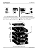
IQ-INT II IQ Interface RS232/RS422 ODEP ENABLE ENABLE IOC P OW E R SPI CH1 CH2 ODEP OFF ENABLE IOC P OW E R SPI CH1 CH2 ODEP OFF ENABLE IOC P OW E R SPI CH1 CH2 OFF DSPI ODEP ENABLE ENABLE IOC P OW E R SPI CH1 CH2 ODEP OFF ENABLE IOC P OW E R SPI CROWN BUS LOOP 2 DSPI CROWN BUS LOOP 1 ENABLE CH1 CH2 ODEP OFF ENABLE IOC P OW E R SPI CH1 CH2 OFF Fig. 3.
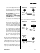
IQ-INT II IQ Interface its lower capacitance. When used with the Crown Bus, a shield serves two purposes: it helps prevent data signals from being transmitted to nearby audio wiring, and helps prevent high external RF levels from interfering with data transmissions. If you must install shielded wire, use a low-capacitance shielded wire like West Penn 452 or equivalent. • If shielded wire is used, only connect the shield at the input connection. Connecting both ends of the shield may cause a ground loop.
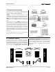
IQ-INT II IQ Interface RJ45 Input IQ-INT II Output RJ45 Output IQ-INT II Fig. 3.5 IQ-INT II Output Connection to RJ45 Input. Fig. 3.6 RJ45 Output Connection to a IQ-INT-II. The IQ components on each Crown Bus loop are connected in succession. Each loop begins and ends with the IQ-INT II. The output of the interface connects to the input of the first unit, then each unit’s output is connected to the next unit’s input until the loop returns to the interface. This is shown in Figure 3.7.
IQ-INT II IQ Interface 3.2 Connecting to a Host Computer PC (RS232) There are two main communication standards supported by the IQ-INT II for serial communication with a host computer. They are RS232 and RS422. RS232 is commonly used with IBM ® PCs and compatibles. Because it uses unbalanced signal wiring, it cannot be used for distances over 50 feet (15.2 m). RS422 uses balanced signal wiring and can be used for distances up to 2,000 feet (610 m) with data grade cable.
IQ-INT II IQ Interface computer (refer to your IQ software manual). Stop bits, data bits and parity checking should be set to their default values. 3.2.2 Communication Settings Before communication can take place between the unit and a host computer, the communication standard must be selected and the communication parameters must be set with switches accessed through an opening in the side of the chassis (see Figure 3.11). • The IQ-INT II can be set as high as 38.4 K baud.
IQ-INT II IQ Interface 4 Technical Information The purpose of the IQ-INT II is to provide a means for the IQ System host computer to communicate with the IQ components. The interface supports RS232, RS422 and RS423 serial data standards. It accepts host computer communication baud rates from 300 to 38,400 and can drive up to 8 independent Crown Bus loops for a high level of fault tolerance.
IQ-INT II IQ Interface 5 Specifications General Internal Controls: An 8-segment DIP switch is used to configure the data rate and other parameters for communication with the host computer. The switch is accessed through an opening in the side of the chassis. Crown Bus Data Communication Protection: The auto-reset feature is controlled by the microprocessor. Optically coupled 20-milliamp current loop receivers provide ground isolation. Data Rate: 38.4 K baud.
IQ-INT II IQ Interface 6 Service Your repaired unit will be returned via UPS ground. Please contact us if other arrangements are required. This unit has very sophisticated circuitry which should only be serviced by a fully trained technician. This is one reason why each unit bears the following label: Always use the original factory pack to transport the unit. CAUTION: To prevent electric shock, do not remove covers. No user serviceable parts inside. Refer servicing to a qualified technician.
Crown Factory Service Information Shipping Address: Crown International, Inc., Factory Service, Plant 2 SW, 1718 W. Mishawaka Rd.