
Manual


IQ-INT II IQ Interface
Page 11
Reference Manual
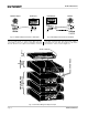
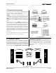
Fig. 4.1 IQ-INT II Circuit Block Diagram
MICRO-
PROCESSOR
POWER
SUPPLY
BAUD
RATE
BAUD
RATE
SERIAL
BUFFER
PARALLEL TO SERIAL
SERIAL TO PARALLEL
EXT.
UART
OPTION
SWITCHES
GENERATOR
SWITCHES
LINE 1
RECEIVER
LINE 2
RECEIVER
LINE 3
RECEIVER
LINE 4
RECEIVER
LINE 4
DRIVER
LINE 3
DRIVER
LINE 2
DRIVER
LINE 1
DRIVER
4 OF 8
LINE RECEIVERS
4 0F 8
LINE DRIVERS
SINGLE POLE
8 POSITION
SWITCH
(ONLY 4 POSITIONS SHOWN)
SINGLE POLE
8 POSITION
SWITCH
(ONLY 4 POSITIONS SHOWN)
DATA BU S
ADDRESS
RX
TX
LINE 1
INPUT
LINE 2
OUTPUT
LINE 2
INPUT
LINE 3
INPUT
LINE 4
INPUT
LINE 1
OUTPUT
LINE 3
OUTPUT
LINE 4
OUTPUT
TO HOST
COMPUTER
11
12
INTERNAL UART
4 Technical Information
The purpose of the
IQ-INT II
is to provide a means for
the
IQ System
host computer to communicate with the
IQ components. The interface supports RS232, RS422
and RS423 serial data standards. It accepts host
computer communication baud rates from 300 to 38,400
and can drive up to 8 independent Crown Bus loops for
a high level of fault tolerance. In addition, the
IQ-INT II
supports both the original
IQ System
and Ucode
protocols, and it provides Crown’s own robust network
transport layer.
Figure 4.1 shows an
IQ-INT ll
block diagram. The unit
has a standard full-wave bridge power supply. Its primary
transformer can be configured by an internal voltage
select switch for either 115 or 230 VAC; however, this
procedure should only be performed by a qualified
service technician. (The unit will operate reliably over a
wide range of voltages with either AC mains
configuration.) A capacitor-coupled half-wave double
circuit is used to generate –5 volts.
The interface is equipped with an auto-reset feature. The
microprocessor generates an auto-reset signal that can
be used as a reliable power-on reset and an automatic
“warm” reset in case control is lost due to noise or other
anomalies.
The baud rate for communication with the host computer
is determined by the baud rate generator which is
controlled by an 8-segment DIP switch (SW1). Other
serial communication parameters such as data bits, stop
bits and parity are also set using SW1.
The interface’s microprocessor communicates with other
IQ components using its internal UART to drive each
loop at 38,400 baud. An external UART is used for
communication with the host computer.
Data from the host computer arrives at the serial buffer
which accepts RS232, RS422, and RS423 data
standards. From here the signal goes to the serial input
of the UART which shifts the data from serial to parallel
before proceeding to the microprocessor where it is
loaded into memory. Next, the interface takes care of
any required checksum calculations and other transport
layer processing. Finally, all of the data bytes are
dumped out the microprocessor’s SIO port (the TX pin)
at 38,400 baud.
The microprocessor controls the input and output
selectors that control which loop will receive data. Data
is sent to the selected line driver, which sends the data
onto the current loop to the appropriate IQ component.
The line receiver takes incoming data from IQ
components and sends it through the input selector to
the microprocessor’s SIO input RX pin. The
microprocessor stores the data in memory and handles
the required transport layer processing. The remaining
protocol data is then sent to the UART as parallel signals.
The UART converts the data from parallel to serial and
moves it to the serial output buffer for transmission to the
host computer.