
Manual

IQ-INT II IQ Interface
Page 7
Reference Manual
its lower capacitance. When used with the Crown
Bus, a shield serves two purposes: it helps prevent
data signals from being transmitted to nearby audio
wiring, and helps prevent high external RF levels
from interfering with data transmissions. If you must
install shielded wire, use a low-capacitance shielded
wire like West Penn 452 or equivalent.
• If shielded wire is used, only connect the shield
at the input connection.
Connecting both ends of
the shield may cause a ground loop.
• The total capacitance for each loop should be
40 nanofarads or less.
Add up the loop’s total
capacitance based on the wire’s rating in picofarads
per foot, and allow approximately 60 picofarads for
each connected IQ component. Experience has
shown that loops with 75 or more components
usually require at least one repeater.
• Add an IQ Repeater
for long loops greater than
1,000 feet (305 m) or when required by high-
capacitance wire. Although repeaters are
recommended for loops longer than 1,000 feet, it is
often possible to set up reliable loops of 2,000 feet
(610 m) or more without a repeater. Although we
recommend shielded wire, unshielded wire typically
has less capacitance and can support longer loops.
• Never use the ground wire in a mic snake.
At
times, it may be convenient to run Crown Bus data
signals to and from stage monitor amplifiers along
unused wires in a mic snake. If this is done, do not
use the ground wire which is normally connected
to pin 1 on an XLR connector, or data noise will be
added to the audio lines. Use only the signal lines
which normally connect to pins 2 and 3 of the XLR’s.
Note: Because typical mic cables have higher
capacitance, the maximum possible Crown Bus
loop will be shorter than low-capacitance twisted-
pair wire.
Outside RF interference is seldom a problem for a Crown
Bus loop—especially if shielded twisted-pair wire is used.
However, there are extreme situations when fiber optic
wiring is recommended. For example, locating a Crown
Bus loop next to an AM radio transmission line may
require fiber optic transceivers and cabling. It may also
be more practical to use fiber optics for extremely long
Crown Bus loops when distances exceed several miles.
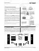
Three different of connectors are used for Crown Bus
wiring on IQ components. These include DIN connectors,
RJ45 connectors, and removable barrier strip plugs. The
IQ-INT II
uses 5-pin DINs for input and 4-pin DINs for
output. Figure 3.2 shows how to connect IQ components
with DIN connectors.
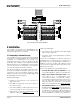
Fig. 3.2 IQ-INT II Output Connection to a DIN Input.
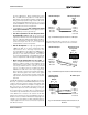
Fig. 3.3 IQ-INT II Output Connection to Barrier Block Input.
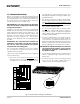
Fig. 3.4 Barrier Block IQ Component Connection to an
IQ-INT II
1 Input (–)
2 Input (+)
3 GND
4 Not used
5 Not used
DIN IQ Component
Input
2
5
3
4
1
Optional Shield
Output (–) 1
Output (+) 2
Not used 3
Not used 4
IQ–INT II Output
23
41
OUT IN
+ – + –
Output (+)
Output (–)
Input (+)
Input (–)
GND
Output (–) 1
Output (+) 2
Not used 3
Not used 4
Barrier Block IQ
Component
Input
IQ–INT II Output
23
41
O
ptional Shield
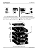
The following examples show how to connect the
IQ-INT II to other IQ components on the Crown Bus:
OUT IN
++–
1 Input (–)
2 Input (+)
3 GND
4 Not used
5 Not used
Output (+)
Output (–)
Input (+)
Input (–)
IQ–INT II Input
2
5
3
4
1
Optional Shield
Barrier Block
IQ Component
Output